 ?Mathematical formulae have been encoded as MathML and are displayed in this HTML version using MathJax in order to improve their display. Uncheck the box to turn MathJax off. This feature requires Javascript. Click on a formula to zoom.
Abstract
The first friction-cycle ergometers of the end of the nineteenth century and the beginning of the 20th century are presented before the description of more recent ergometers such as Fleisch ergometer (1954), ErgomécaTM (1985), sinus-balance ergometer, and weight-basket loaded ergometer. The limits of each ergometer are debated. The interest of friction-loaded ergometers was renewed with the proposal of different protocols enabling the assessment of maximal power during short all-out sprints on a cycle ergometer. These protocols are succinctly presented: corrected peak power protocol, force-speed test during repeated all-out sprints against different loads, torque–velocity relationship during a single all-out sprint. The different calibration procedures (static, dynamic, and physiological calibrations) of friction-loaded ergometers are described before the presentation of their results in the literature. Some improvements for the future friction-loaded ergometers are presented at the end of the paper.
Public Interest Statement
The history of the first friction-cycle ergometers (end of the nineteenth century) is presented before the description of more recent ergometers: Fleisch ergometer (1954), sinus-balance ergometer (von Döbeln, Citation1954), ErgomécaTM (1985), and weight-basket loaded ergometers. The interests and limits of each ergometer are debated. The interest of these friction-loaded ergometers was renewed with the proposal of different protocols enabling the assessment of maximal power during short maximal sprints on a cycle ergometer. These protocols are succinctly presented. The different calibration procedures of the cycles ergometers and theirs results are also presented: static calibration (calibration of the braking mechanism without pedal rotation), dynamic calibration (comparison of the displayed power and the torque exerted by a motor on the cranks), and physiological calibration (measure of oxygen uptake during cycling at different power outputs). Some improvements for the future friction-loaded ergometers are presented at the end of the paper.
1. Introduction
Treadmills and cycle ergometers are the devices generally used in medical and physiological testing or aerobic training. Many kinds of cycle ergometers have been designed in relation to their usage. The braking mechanism of most of these ergometers is either electromagnetical or mechanical or aerodynamical.
In experiments carried out between 1898 and 1900, Atwater and Benedict (cited in Benedict & Cady, Citation1912) studied human metabolism at rest and during long lasting exercises performed on a cycle ergometer that consisted of a pulley mounted on the shaft of a small dynamo pressing against the rear wheel of an ordinary bicycle. Thereafter, Benedict and Carpenter (Citation1909) described and constructed an electromagnetically braked cycle ergometer that was modified by Benedict and Cady (Citation1912). The work done per revolution was estimated from the intensity of the current employed for actuating the magnets. However, the work done per revolution depended not only on the magnetizing current but also varied with the speed. Krogh, Nobel prize in medicine in 1920, described an electromagnetic ergometer measuring the reaction torque acting on the magnets by means of a balance, instead of measuring the magnetizing current as in the Benedict ergometer (Krogh, Citation1913). Thereafter, many improvements in electromagnetic cycle ergometers were proposed (Atkins & Nicholson, Citation1963; Atkins & Nünlist, Citation1966; Harrison Citation1967; Kelso, Hellebrandt, & Madison, Citation1933; Tuttle & Wendler, Citation1945; Williams, Barnes, & Signorile Citation1988). But the most significant advance in electromagnetic ergometer was the description of hyperbolic ergometers, i.e. ergometers with constant work power at varying pedal rate (Holmgren & Mattsson, Citation1954; Lanooy & Bonjer, Citation1956). Indeed, errors in pedal cadence are probably one of the main causes of errors in power output with non-hyperbolic ergometers in subjects who are not habituated to cycling exercises. Nowadays, the electrically braked ergometers generally includes a compensatory circuitry measuring cadence and torque continuously to maintain a constant power input from the subjects over a range of pedal rates (e.g. 40–100 rpm). Expensive hyperbolic electro-magnetic cycle ergometers are generally used in medicine and physiology for the stress tests in cardiac patients and the evaluation of aerobic metabolism (maximal oxygen uptake). Generally, the users of these hyperbolic cycle ergometers do not perform any calibration procedure but rely entirely on the original calibration by manufacturer. Indeed, dynamic calibration procedure needs an expensive calibrator and is time consuming. However, hyperbolic ergometers cannot be used for the evaluation of maximal anaerobic power (Driss & Vandewalle, Citation2013). As for car motors, the rotational speed optimal for maximal anaerobic power (100 rpm in elite endurance athletes up to 130 rpm in elite sprinters) is higher than the rotational speed optimal for the efficiency (60–90 rpm) of submaximal and maximal aerobic exercises. Therefore, the range of pedal cadence with a hyperbolic ergometer is adapted to the study of aerobic metabolism (submaximal and “maximal” exercises) but, generally, not to the evaluation of anaerobic metabolism (“supramaximal” exercise). In addition, the durations of the all-out anaerobic exercises are too short (a few seconds) for the adjustment of power by hyperbolic cycle ergometers and the required power outputs (600 W in endurance athletes up to 2,000 W in elite sprinters) are generally higher than the maximal powers of these ergometers.
Aerodynamically braked ergometers have been used for anaerobic testing (Withers, Van Der Ploeg, & Finn, Citation1993). For aerodynamical ergometers, resistance is not only proportional to the square of pedal rate but also depends on air density, that is, on barometric pressure, temperature, and air humidity. In contrast with the mechanical and electromagnetical ergometers, power output is proportional to the cube of pedal rate with aerodynamical-braked ergometer. For example, the errors in power-output corresponding to a one-revolution error in pedal rate are equal to 5 and 3.8% at 60 and 80 rpm, respectively. These ergometers are mainly used for training (cycling, rowing) but seldom in physiological and medical testing, although the accuracy of these ergometers has been found correct in studies comparing the accuracy of different kinds of cycle ergometers (Balmer, Davison, Coleman, & Bird, Citation2000; Maxwell et al., Citation1998).
Friction-loaded cycle ergometer is less expensive, do not need electricity, and can be statically calibrated. On the other hand, power of the friction-braked ergometer depends on pedal cadence which is generally given by a metronome and is displayed on an analogical tachometer or a digital device. Therefore, the hyperbolic electromagnetic ergometer is preferred for the medical testing in subjects not habituated to cycling exercises. However, the interest of friction-loaded cycle ergometers was renewed when different protocols were proposed for anaerobic metabolism testing with this kind of ergometers (Ayalon, Inbar, & Bar-Or, Citation1974; Bar-Or, Citation1987; Driss & Vandewalle, Citation2013). Moreover, some maximal anaerobic power tests based on the relationship between pedal rate and maximal torque (Sargeant, Hoinville, & Young, Citation1981; Vandewalle, Pérès, Heller, & Monod, Citation1985) cannot be performed with hyperbolic ergometers. Different models of friction-loaded cycle ergometers are available but most of the users do not know which ones are the most suitable (testing and/or training, aerobic and/or anaerobic exercises, children and/or adults …) and how to assure the maintenance and calibration of these ergometers.
The present paper is focused on the friction-braked cycle ergometers used in physiology and medicine. It begins with the evolution and description of the first cycle ergometers before the presentation of the friction-loaded ergometer currently used in medical and physiological studies (Hollmann & Prinz, Citation1991). Thereafter, the mechanical basis of the measurement of maximal anaerobic power with friction-brake ergometers is presented. The last chapters concern the calibration methods, the maintenance, and the future of friction-loaded cycle ergometers.
2. Friction-loaded ergometer: Past
Mechanically braked cycle ergometers are based on the transformation of power output in heat by dissipative friction forces. The first ergometers were derived from the dynamometers and brakes which have been proposed by engineers for the first industrial machines: Prony’s brake and rope brakes.
2.1. Prony cycle ergometer
In Austria, a crank ergometer called “Ergostat” (Gaertner, Citation1887) based on the principle of the Prony brake was used in the study of exercises performed with the arms. The same kind of crank ergometer was used by Zuntz (Citation1899) at Berlin. It is likely that the first cycle ergometer was the ergometer constructed in France by E. Bouny in collaboration with J.E. Marey, a pioneer of motion analysis (Bouny, Citation1896a, Citation1896b). This cycle ergometer was made of a bicycle whose ordinary wheel was replaced with a flywheel and a Prony brake mounted on the same axle. The work performed on this device was compared with the simultaneous measures of force by means of Marey’s ergometric pedals modified by Bouny. The work measured with ergometric pedal was approximately 5% higher than the work measured with the Prony brake, which was attributed to energy loss in the transmission between pedal and braking device. Although it is theoretically possible to design Prony brakes with constant torque (Poncelet, Citation1876), the arm lever of a Prony brake tends to oscillate (Jervis-Smith, Citation1915). Therefore, the position of the arm lever of the Prony brake and pedal rate was continuously recorded to know the amount of work performed on the Bouny’s ergometer. In fact, the purpose of Bouny was not the measurement of work in man but the validation of his modifications of Marey’s ergometric pedal. An adaptation of the Prony brake with a lever exerting a torque on the ergometer flywheel by means of a brake shoe has been presented by Harrison (Citation1967) but has not been used in physiological or medical studies.
2.2. Rope brake ergometers: General principles
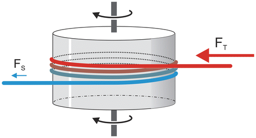
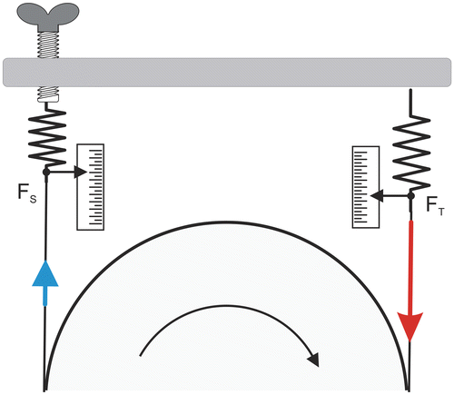
Let a rope wrapped around a rotating cylinder (Figure ), the force FT exerted on the tight extremity of the rope by the friction force of the rope sliding on the cylinder is given by the following equation:(1)
(1)
Figure 1. Force acting on the tight (FT) and slack (FS) ends of a rope winding around a rotating cylinder.
where FS is the force exerted on the slack extremity of the rope, θ corresponds to the winding (angle in radian) of the rope around the cylinder, and μ is the dynamic friction coefficient. The value of FS necessary to the production of FT is given by the following equation:(2)
(2)
If there is no other external force acting on the rope, the force F exerted by the rotating cylinder is:(3)
(3)
(4)
(4)
(5)
(5)
When the rope consists of two elements in series (e.g. a belt and a rope), the values of FT and FS are:
(6)
(6)
If θ1 = aθ and θ2 = (1 − a)θ
where θ1 and μ1 correspond to the winding and friction coefficient of the belt, whereas θ2 and μ2 correspond to the winding and friction coefficient of the rope.
Working with one of the first transatlantic cable companies, W. Thomson (Lord Kelvin) registered a patent in 1858 for the improvement of the braking of the cable-laying system (cited in Jervis-Smith, Citation1915). This friction brake consisted of a rope wrapped around the circumference of a rotating wheel, with a weight W applied at one end and a spring balance fixed to the other end. In this brake, the value of FT was equal to W and FS to the force that was registered by the spring balance. If product μθ was sufficiently large, the value of k was high and FS was low, which rendered the errors in the observation of the spring balance negligible.
However, this friction-brake design was not used in most of the first friction-braked cycle ergometers. For example in the Martin’s ergometer used in the studies by Dickinson (Citation1928), the values of FT and FS were given by spring-dynamometers linked at both extremities of the belt. The friction force (FFW) of the flywheel sliding on the belt was equal to the difference of FT and FS (Figure ).
Figure 2. Braking mechanism of the first friction-loaded ergometers; braking force acting on the flywheel (FFW) is equal to the difference between tight (FT) and slack (FS) forces which were displayed by means of scale.
2.2.1. Amar’s “Cycle ergométrique”
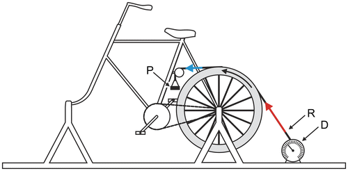
In his study on the efficiency of human machine, Amar used an ergometer (Figure ) made of the frame of a bicycle with a 36 kg flywheel in the place of the ordinary wheel (Amar, Citation1909). A steel ribbon was laid in a channel in the circumference of the flywheel with one end attached to a traction dynamometer and the other end carrying a platform for weights. But, in contrast with the friction-brake designed by Lord Kelvin, the weight-platform was attached to the slack end of the ribbon. One pedal revolution corresponded to three flywheel revolutions and a point of the circumference of the wheel travelled 6.18 m as the perimeter of the wheel measured 2.06 m. Therefore, power output was close to 1 W for a pedal rate equal to 1 rpm and a one kilogram-force difference between FT (force measured by the dynamometer) and FS (weight on the platform), as 1 kgm min−1 is equal to 6.11 W.
Figure 3. Amar’s cycle ergometer; D, P, and R correspond to the dynamometer, platform for weight, and steel ribbon, respectively.
Twenty years later, Dickinson replaced one spring-dynamometer (slack or tight end of the rope?) with a weight to improve the accuracy of the estimation of work at low braking torque in her study on the efficiency of bicycle pedaling (Dickinson, Citation1929). Holzer and Kalinka (Citation1935) presented a cycle ergometer based on the same mechanism: FS was equal to a weight and FT was measured with a dynamometer as in Amar’s ergometer. However, in the description of the Holzer–Kalinka ergometer by Mellerowicz (Citation1962), FT and FS were swapped: FT was equal to a weight and FS was measured with a dynamometer in agreement with the friction-brake designed by Lord Kelvin.
2.2.2. Fleisch ergometer
In the same year Carpentier (Citation1880) and Thomson (cited by Beaumont, Citation1889) presented, the same kind of brake dynamometers (Figure ) “in which the same principle of automatic government of friction is employed. In order to keep eμθ … constant, θ is made to vary inversely as μ.” (Jervis-Smith, Citation1915). This kind of brake dynamometers consists of two pulleys of the same diameter placed side by side on a revolving shaft. The first pulley (fast pulley) is rigidly fixed to the shaft, the other (loose pulley) runs freely on the shaft.
Figure 4. Thomson brake (drawing adapted from Beaumont, Citation1889, p. 33; Jervis-Smith, Citation1915, p. 82).
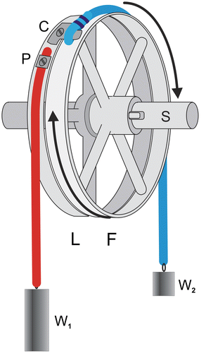
Fleisch (Citation1950) who previously invented the differential pneumotachometer in 1925 presented a friction-loaded ergometer whose braking torque was constant. This cycle ergometer (Figure ) was based on the Carpentier–Thomson brake. The braking force acting on the flywheel (FFW) is equal to the difference between FT and FS which depends on the friction coefficient (μ) and the winding (θ) of the belt (B) around the flywheel (fast pulley, F):
Figure 5. Fleisch ergometer; F et L fast et loose wheels, C connection between pulley L and belt B that is attached to weight W2 at the other end.
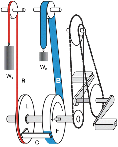
If FT and FS are set by weights W1 and W2, the value of FFW is constant if θ adequately increases when μ decreases and vice versa. Weight W1 is attached to a rope R wrapped around a loose pulley L that is linked to belt B by a rigid link C. Therefore, the forces acting on belt B that rubs on the fast pulley are: weight W2, the friction force (FTW), and the traction exerted by connection C. As the traction exerted by connection C is equal to weight W1, FFW is equal to the difference between W1 and W2. When FFW is lower than the difference W1 − W2, the mass W1 moves down and connection C moves up: the winding of the belt around F and FTFW increase. Inversely, when FFW is higher than the difference W1 − W2, the mass W1 moves up and connection C moves down: both the winding of the belt around F and FTPW increase or decrease.
With the previous ergometers, it was difficult to set a given braking torque because it was impossible to change FT without modifying FS. In addition to the steadiness of braking torque, Fleisch ergometer presented a second advantage: it was easy to set a given braking torque because FFW was equal to W1 − W2. However, the use of this ergometer was limited to some laboratories probably because it was expansive when compared with the sinus-balance cycle ergometer which was proposed a few years later.
2.2.3. ErgomécaTM cycle ergometer
Brue, Melin, Lamande, and Philippe (Citation1983) presented a friction-loaded cycle ergometer (ErgomécaTM, Sorem, Toulon, France) which was designed for aerobic and anaerobic testing and whose belt tension adjustment was achieved by a cam (Figure ). This ergometer enabled the use of a large range of loads (0–196 N, with 2.5 N increments) by means of a roman steelyard mechanism. This ergometer was mainly used in the French army. In addition to the usual iron flywheel, this ergometer was supplied with a light aluminum flywheel and its crank length could be changed. Therefore, this ergometer was also used in many studies on the development of maximal anaerobic power during growth in boys and girls (Bedu et al., Citation1991; Van Praagh, Fellmann, Bedu, Falgairette, & Coudert, Citation1990).
Figure 6. A, LB et LP arms of forces FB and P; FT and FS, tensions of the tight and slack ends of the belt; O1, O2, and O3, axles of the flywheel, cam, and pulley, respectively; O4 pivot of the roman steelyard; B, h1, and h2 lever-arms of FS1 and FS2, respectively; Wc and hc weight of the cam and its lever arm.
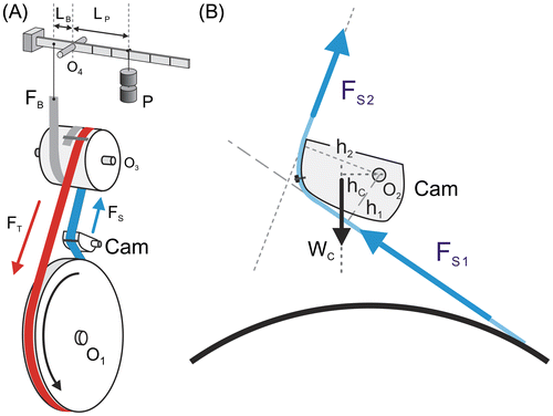
Force FB multiplied by length LB was equal to the weight of the counterweight P multiplied by the distance Lp of the counterweight (P) from the pivot. The values of LP and P were adjusted to obtain the required force FB:
It was assumed that FFW was equal to the difference between FT and FS (Figure (A)). The belt tension was automatically adjusted by a cam. When FFW was higher than FT − FS, the cam moved up and the belt tension decreased. When FFW was lower than FT − FS, the cam moved down and the belt tension increased.
In fact, FFW was equal to FT − FS1 and FB was equal to FT − FS2 (Figure (B)). It was assumed that FS1 and FS2 were equal, which was not true. At equilibrium, the principal moment exerted on the cam was equal to zero. If the weight of the cam was not taken into account, the value of FB was different from FFW:
where RS1 was the reaction force exerted by the belt on the cam (RS1 = −FS1).
The error in FFW depended on the position of the cam. FB was either an underestimation of FFW (h1 < h2) or an overestimation (h1 > h2) of FFW.
When the weight of the cam was taken into account, FB was equal to:
Hence,
Therefore, the error of FFW was either partly compensated by the torque exerted by the cam (h1 < h2) or increased (h1 > h2).
Van Praagh, Bedu, Roddier, and Coudert (Citation1992) carried out a dynamic calibration of the ErgomécaTM cycle ergometer by raising the ergometer onto a platform and adding to the crank shaft a pulley to which different weights were attached. The falling weights provided the input torque that accelerated the flywheel. The accelerations were measured for different braking forces (FB). The difference between FB and actual braking force computed for FB equal to 0, 4.91, 7.36, and 9.81 N was equal to 0.10, 0.47, 0.38, and 0.28 N. Therefore, the underestimation of power output decreased from 9.6 to 2.9% for FB equal to 4.91 and 9.81 N, respectively.
3. Friction-loaded ergometers: Present
3.1. Sinus-balance cycle ergometer
von Döbeln (Citation1954) designed a cycle ergometer whose the difference between FT and FS and the value of FFW was automatically given by a sinus-balance system (Figure ). The resulting torque r(FT − FS) exerted by the belt on the pulley was counterbalanced by the torque exerted by the sinus-balance system (TS-B).
Figure 7. Von Döbeln ergometer.
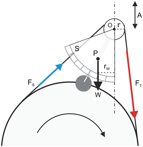
where W and rW were the weight and the arm lever of the center of mass of the pendulum, respectively. The value of FFW was given by the position of the pendulum (Figure ) in front of a force scale (S).
In the von Döbeln ergometer, the belt tension, brake torque, and pendulum position are adjusted by modifying the distance between the pulley axle (O) and the flywheel axis (A in Figure ). The underlying assumption was that there was no external force acting on the belt-pulley system except the frictional force exerted at the flywheel and the force exerted by the sinus-balance system (W). The gravitational forces exerted on the slack and tight belt and their difference could be considered as negligible. The higher the tensions in the slight and tight belts, the higher the frictional force at the pulley axis (O) should be. However, this frictional force was minimized by ball-bearings.
After this publication, a sinus-balance ergometer was manufactured by MonarkTM (MonarkTM, Varberg, Sweden) and largely used in physical testing of the athletes. However, this latter ergometer did not exactly correspond to the model proposed by von Döbeln. Indeed, the belt tension was not adjusted by modifying the distance between the pulley axle and the flywheel axle but by a pressure on the slack belt (Figure ), which introduced a supplementary external force. The error due to this external force was minimized by a ball-bearing and was considered as low.
Figure 8. Monark sinus-balance cycle ergometer.
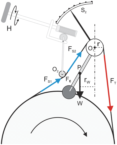
In contrast with Fleisch ergometer, FFW varies if the friction coefficient is not constant (e.g. because of the effect of temperature). Therefore, it is necessary to adjust the belt tension to maintain the brake torque by means of a handle (H in Figure ). Moreover, it is not possible to set the brake force instantaneously before cycling with sinus-balance ergometers because the resistance must be set while the flywheel is moving.
3.2. Weight-basket loaded ergometer
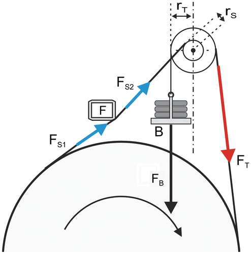
A new MonarkTM ergometer with weight basket (model 864) was proposed (Figure ). In this model, the resulting torque exerted on the pulley by the belt is counterbalanced by the torque (TB) exerted by a basket whose weight (FB) is adjusted with additional masses. Small ribbons (R1 and R2), limit the vertical displacement of the basket. The tension of the belt is adjusted by means of a turnbuckle before the exercise.
Figure 9. Weight-basket loaded cycle ergometer.
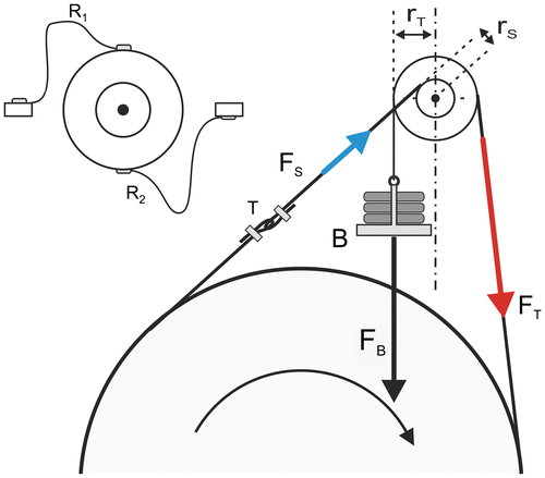
At equilibrium:
In contrast with the sinus-balance model proposed by von Döbeln, the radius of the pulley is different for the tight belt and slack rope (Figure ). When TB is higher than the difference between TT and TS, the basket moves down, which provokes a winding of the belt around a large pulley (rT) and a unwinding of the rope around the smaller pulley (rS). Therefore, the belt-rope tension increases until the difference between TT and TS is equal to TB. Inversely, when TB is lower than the difference TT − TS, the basket moves up and the belt-rope tension decreases. The value of FFW is given by Equation 4.
(7)
(7)
(8)
(8)
(9)
(9)
(10)
(10)
Therefore, FB is an overestimation (Equation 9) of FFW equal to FS(1 − rS/rT). The value of FS was minimized by prolonging the belt with a rope (Figure (B)), which added 360° to the winding (θ equal to 590°, approximately). Ratio rS/rT is equal to 0.45 and, therefore, FB corresponded to a FFW overestimation equal to 0.55 FS.
Figure 10. A, belt in the sinus-balance model; B, belt and rope in the basket-loaded ergometers; C, digging of small grooves in the circumference of aluminum flywheel; D, 3-turn rope.
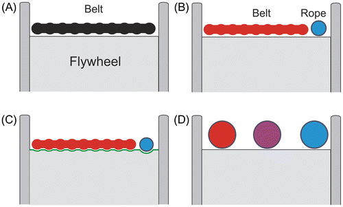
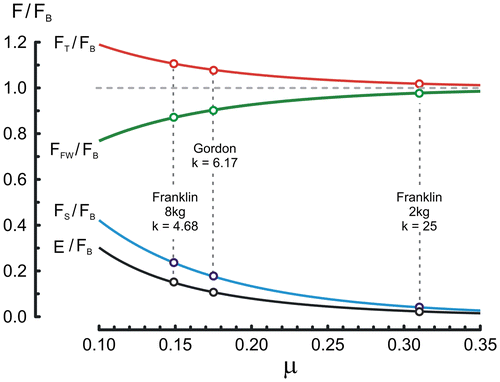
We observed that the belt warp “digs” small circular grooves in the aluminum flywheels after several months of use at high power outputs. The flat belt progressively becomes similar to a multiple V-belt (Figure (C)), which results in an increase in the apparent coefficient of friction. Given the negative exponential relationship between FT, FS, θ, and μ, the tension of the slack rope was probably very low. For example, at low brake torques (FB = 10 or 20 N), the slack rope was not straight but curved by the only action of gravity. Therefore, the overestimation due to the difference between radii rS and rT was probably negligible. The relationships (Equations 7–10) between μ, FT, FS and error in FFW for θ = 10.4 rad and rS/rT = 0.45 are presented in Figure .
Figure 11. Relationships between μ, FT, FS, and error in FFW expressed as fractions of FB.
The first MonarkTM ergometer with weight basket (model 864) has been adapted for exercises at very high power output by modifying the design of the frame and increasing the flywheel inertia (models 824 and 834). Indeed, angular speed varies during a pedal revolution in function of the torques exerted on the cranks and the flywheel. At top dead center or bottom dead center, the pedal angular speed largely decreases when brake torque is high and flywheel inertia is low. Therefore, the aluminum flywheel of the MonarkTM ergometer 864 was replaced with a heavier iron flywheel (22 kg instead of 10 kg) in models 824 and 834 to facilitate cycling against high brake torques. The coefficient of friction μ of the rope on the flywheel depends on the metal (iron or aluminum) and its state. The values of μ are close for a belt sliding on iron and aluminum. But after the digging of small grooves, it is likely that FS is lower with aluminum flywheel than with an iron flywheel.
4. Friction-loaded cycle ergometer and short all-out exercises
Until the years 1970–1980, the physical examination of athletes mainly consisted in the study of cardiovascular performances and endurance indices (maximal oxygen uptake, maximal aerobic power or speed), only. The pertinence of these aerobic tests was highly debatable for athletes specialized in short exercises whose performances were not limited by cardiovascular adaptation and aerobic metabolism. Moreover, it became obvious that the assessment of mechanical factors (strength, speed, and maximal mechanical power) determining athletic performances should be added to the usual tests mainly focused on bioenergetics. The Wingate anaerobic test (Ayalon et al., Citation1974; Bar-Or, Citation1978, Citation1987) consists in pedaling with maximal (all-out) effort for 30 s against a constant braking force (7.5% body mass for a MonarkTM ergometer). Three indices of anaerobic performance are computed: peak power output (PP), mean power output over the 30 s of the whole test, and a fatigue index equal to the difference between peak power output and the lowest power output. Other durations of all-out cycling tests were proposed such as a 40-s all-out test against a constant resistance equal to 5.5 kg (Katch, Weltman, Martin, & Gray, Citation1977; Katch, Weltman, & Traeger, Citation1976). The fatigue index was the least reliable of the three Wingate test indices, and its validity was questioned as it largely depends on aerobic performance. The validity of mean power as an index of anaerobic capacity is as questionable as the aerobic metabolism provides a higher contribution to this energy demand in endurance athlete than in sprint athletes (Granier, Mercier, Mercier, Anselme, & Prefaut, Citation1995). Therefore, peak power during a Wingate test is probably the only index that merits to be measured, provided that the resistance is optimal. But there is no consensus on the optimal resistance: 7.5% (Ayalon et al., Citation1974), 8.7% (Dotan & Bar-Or, Citation1983), or 10.0% body mass (Vandewalle, Pérès, et al., Citation1985). Although the validity of the Wingate test is debated, it is likely that this anaerobic test is the all-out cycling test, which is currently the most often used, not only in athlete testing but also in studies on the biological adaptations to strenuous exercises. The absence of consensus about the optimal resistance for the Wingate test can be explained by the results of the experimental studies on mechanical properties of isolated muscles achieved between 1935 and 1940 (Fenn & Marsh, Citation1935; Hill, Citation1938). These studies have found: (1) that the force production depends on the speed of shortening; (2) that maximal muscle power corresponds to optimal values of force (Fopt) and speed (Vopt); (3) that maximal muscle power, Fopt and Vopt largely depend on the types of muscle fibers. Because of the dependence of maximal muscle power, Vopt, and Fopt on muscle fiber types, it is difficult to know the optimal conditions (loads or pedal rates) which correspond to the production of Pmax before the completion of cycling tests. As a consequence, different protocols have been proposed for the determination of force–pedal rate relation in cycling and Pmax on isokinetic cycle ergometers (Sargeant et al., Citation1981) and friction-braked ergometers (Nakamura, Mutoh, & Miyashita, Citation1985; Pérès, Vandewalle, & Monod, Citation1981; Vandewalle, Pérès, et al., Citation1985; Vandewalle, Peres, Heller, Panel, & Monod, Citation1987; Vandewalle, Pérès, & Monod, Citation1983).
4.1. Force-speed test and maximal power
During an all-out sprint on a cycle ergometer, the force exerted on the pedal is used not only for the rotation of the flywheel against braking force FFW but also for the acceleration of the flywheel up to peak pedal rate (Vpeak). However, at Vpeak, flywheel acceleration is equal to zero, and the force exerted on the pedal is used for the rotation against FFW, only. Linear relationships (Figure ) between resistance and Vpeak have been observed for short all-out sprints on friction-loaded ergometers (Nakamura et al., Citation1985; Pérès et al., Citation1981; Vandewalle, Pérès, et al., Citation1985; Vandewalle, Peres, Heller, Panel, & Monod, Citation1987; Vandewalle, Pérès, & Monod, Citation1983). This linear relationship was confirmed by a modeling approach (Yoshihuku & Herzog, Citation1996). Time to Vpeak is approximately equal to 3–3.5 s for all the loads (Lakomy, Citation1986; Seck, Vandewalle, Decrops, & Monod, Citation1995; Winter et al., Citation1996). The flywheel inertia is probably not adapted to small subjects, which partly explains why the delay to Vpeak is higher in children (Seck, Vandewalle, & Monod, Citation1991). However, the effect of an early fatigue (Kyle & Caiozzo, Citation1986) due to an increase in the delay to Vpeak cannot explain the low maximal power output in children (Ratel, Omari, Duché, Bedu, & Coudert, Citation1996). Nonetheless, this fatigue effect should be more important with the use of cycle ergometers with 22 kg flywheel instead of 10 kg, especially in children.
Figure 12. In A, time–frequency curves during all-out sprints against different loads on a Monark 864 cycle ergometer; in B, relationship between load and peak frequency (Vpeak).
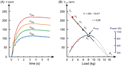
The maximal power Pmax can be calculated from the linear relationship between resistance and Vpeak or its intercepts with the resistance axis (F0) and the pedal rate axis (V0). Pmax corresponds to a resistance equal to 0.5 F0 and an optimal pedal rate (Vopt) equal to 0.5V0. Therefore, Pmax is equal to 0.25V0F0. Interestingly, F0 and Vopt are significantly correlated with strength indices (Driss, Vandewalle, Le Chevalier, & Monod, Citation2002) or muscle fiber types (Hautier, Linossier, Belli, Lacour, & Arsac, Citation1996), respectively. Similarly, Vopt during sprint cycling was significantly correlated to vastus lateralis MHC-II (myosin heavy chain of fast muscle fibers) composition (Pearson, Cobbold, Orrell, & Harridge, Citation2006). Therefore, force-speed tests on friction-loaded ergometers could be used to estimate the muscular strength and contractility in addition to Pmax.
In theory, force-speed tests on friction-loaded ergometers could be used to estimate the muscular strength and contractility. Unfortunately, the values of V0 and F0 depend not only on muscle properties but also on crank length. The effects of crank length on V0, F0, and Pmax were studied in small subjects, that is, children and women (Martin, Malina, & Spirduso, Citation2002; Martin & Spirduso, Citation2001; Vandewalle, Heller, Pérès, & Monod, Citation1985). The value of V0 decreased with long pedal cranks, which partly explains the lower value of V0 in women or in children tested with cycle ergometers designed for adults (Martin et al., Citation2002; Vandewalle, Heller, et al., Citation1985). However, the crank length had opposite effects on F0 and V0: F0 increased with long pedal cranks. Consequently, there was no significant effect of crank dimension on Pmax as it was previously found for the Wingate test (Inbar, Dotan, Trousil, & Dvir, Citation1983). It is likely that the optimal crank length for V0 is about 20% of leg length (Martin et al., Citation2002).
4.2. Maximal power corrected for flywheel acceleration
Lakomy (Citation1985, Citation1986) and Bassett (Citation1989) proposed to calculate the force necessary for flywheel acceleration and to transform this force in an equivalent resistance (Facc) and to add Facc and FFW (Fcorr = Facc + FFW). Power output during each revolution (Pcorr) is equal to the product of the speed during this revolution (Vrev) and Fcorr (Pcorr = VrevFcorr). Given the relationship between force and pedal rate, Fcorr decreases while Vrev increases up to peak pedal rate. Corrected Peak Power (PPcorr) corresponds to the maximal value of Pcorr during the acceleration phase. Therefore, it is theoretically possible to measure the maximal power from the data collected during a single all-out sprints instead of 4–6 sprints against different loads with the force-speed tests. On the other hand, this protocol does not enable the determination of parameters V0 and F0, that is, indices of muscle strength and contractility.
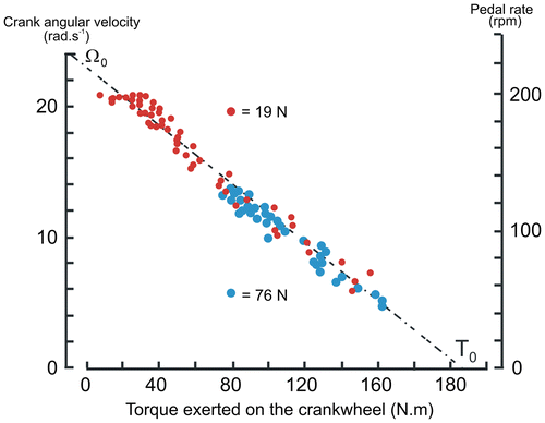
Moreover, time to PPcorr increases with the resistance (Lakomy, Citation1986; Seck et al., Citation1995; Winter et al., Citation1996) and is approximately equal to 1.0 and 3.0 s for FB equal to 19 and 76 on Figure . If there were no fatigue during short all-out sprints, PPcorr should be independent of the resistance and should be equal to Pmax. At low loads, Pcorr is approximately 10% greater than Pmax (Seck et al., Citation1995; Winter et al., Citation1996). The lower value of Pmax compared to PPcorr was interpreted as an effect of early fatigue (Kyle & Caiozzo, Citation1986) because time to PPcorr is shorter than time to Vpeak. For the same reason, PPcorr was not independent of resistance in the study by Lakomy (Citation1986): PPcorr decreases (about 10%) with the increase in resistance probably because of a fatigue effect as PPcorr are obtained later with high loads. In this study by Lakomy (Citation1986), PPcorr also depends on sampling time (0.5 or 1 s), and it was found that it would be better to measure mean power over one revolution instead of mean power over a given time.
Figure 13. Time–power output curves computed during all-out sprints on basket-loaded cycle ergometer against loads equal to 19 N (red curve) and 76 N (blue curve).
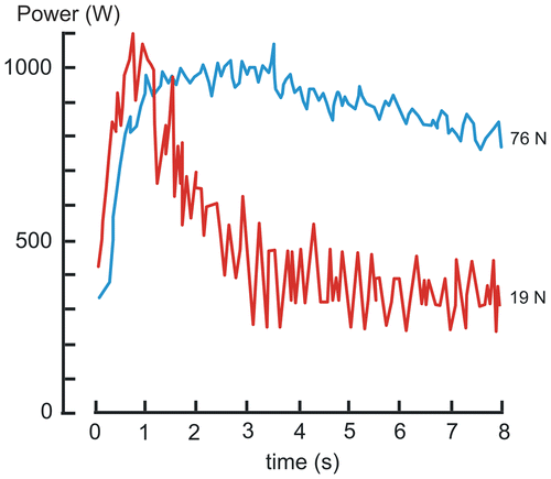
Moreover, the reliability of PPcorr is lower than the reliability of Pmax. In the study by Winter et al. (Citation1996), the test–retest coefficient of correlation is lower for PPcorr than for Pmax: 0.530 versus 0.972 in men and 0.922 versus 0.952 in women. In the same study, the coefficients of variation (CV) of PPcorr are higher in the men (6.9% for PPcorr versus 2.7% for Pmax) but not in women (3.7% for PPcorr versus 4.2% for Pmax). Similarly, for arm exercises, CV was 2.8% for Pmax and 4.5% for PPcorr (Smith, Price, Davison, Scott, & Balmer, Citation2007). It is likely that the lower reliability of PPcorr is explained by oscillations of Pcorr (Figure ) Different causes of the oscillations of Pcorr during an all-out sprint has been presented in the paper by Seck et al. (Citation1995) (see Appendix 1). In a study comparing the results obtained with the protocol proposed by Lakomy (PPcorr during the acceleration phase) and the optimization procedures (force-velocity test) Winter et al. (Citation1996) concluded that “This adds further support to the suggestion that the use of ‘power’ with optimization procedures has securer foundations than those enjoyed by correction procedures.”
4.3. Torque–speed relationship during single all-out sprints
The determination of a torque–speed relationship during a single all-out sprint (Seck et al., Citation1995) on a MonarkTM 864 ergometer (Figure ) was directly derived from the study by Lakomy on the correction of peak power. The relationship between crank torque (T) and crank angular speed (ω) was studied during the acceleration phase of short (<7 s) all-out sprints. The mean crank angular speed ω during each revolution was measured up to peak speed. For each revolution, the mean torque T exerted on the pedal was calculated as equal to the sum of Tacc (the mean torque necessary for flywheel acceleration during each revolution) and TB (the torque necessary for flywheel rotation against FB) as in the study by Lakomy (Citation1985). The T–ω relationship was linear (Figure ) as previously found for the load–Vpeak relationship.
Figure 14. Relationship between the computed torque exerted on the crankwheel and crank angular speed (or pedal rate) during all-out sprints against two loads (19 N red points and 76 N blue points) in the same subject.
A pure inertial resistance (TB = 0) was experimented with the use of an intermediate gear drive which increased the gear ratio to 7.43:1 instead of 3.71:1 (Martin, Wagner, & Coyle, Citation1997). The mean crank torque over one revolution (T) was linearly related to the mean pedal rate (V) over one revolution.
4.4. Limits of the measure of Pmax
Performance in many exercises as jumping, throwing, sprinting depends on impulse-generating capabilities rather than maximal power output. The question of the measure of impulse and power during maximal exercises has been debated many years ago (Adamson & Whitney, Citation1971). The impulse produced by the muscles depends on muscle activation, series elastic components, and muscle fiber types. The external work is not equal to the work produced by the muscle. In cycling, the work produced by the muscles is not only transformed in work at the crank level but is also used to move the leg segments and increase their mechanical energy, that is the sum of potential and kinetic energy. Similarly, “external” impulse in cycling is not equal to the impulse produced by the muscles. Left and right cranks are linked together by a rigid axle and a fraction of the impulse exerted by the descending leg increases the momentum of the ascending leg. Moreover, cycling corresponds to a movement with, at least, two degrees of freedom and the interpretation of the impulse exerted on the cranks needs 3D-dynamometric pedals and transducers measuring the crank and pedal angles and a movement analysis device (e.g. video camera).
In contrast with Fopt and Vopt, maximal muscular power is theoretically independent of muscle dimensions (length and thickness) and architecture (pennation angle) when normalized to muscle mass. The power output measured during short all-out cycling exercises (Pmax) is assumed to be related to maximal muscle power. In contrast with F0 and V0, Pmax does not depend on crank length. Moreover, it is likely that the reliability of Pmax is better than the reliability of V0 or F0 (Driss & Vandewalle, Citation2013). For all these reasons, Pmax that is relatively easy to measure is often the only variable computed during short all-out exercises on a cycle ergometer. However, mean power output over one pedal revolution depends not only on muscle fiber types but also on the rate of muscle activation, series elastic components, and coordination of hip, knee, and ankle muscle groups. Therefore, the interpretation of Pmax must be cautious.
5. Calibration
Cycle ergometers are designed to provide accurate measurement of power output during training or testing. However, the displayed power is often significantly different from the power actually produced. The first causes of this difference are the errors due to the torque setting mechanism. This error can be estimated by static calibration. Comparing the work performed on a prony cycle ergometer and the data of a dynamometric pedal, Bouny (Citation1896b) concluded “The work measured for both feet surpassed about 5% the brake work. This was probably due to the resistance of the pedal axles, roller chain, chainwheel axle and the axle of the wheel”. Static calibration does not take into account the frictional resistance at each stage of the transmission from the pedal shaft to the flywheel axle. For the usual bicycles, this energy loss is often considered to be in the order of 5–9% (Marks, Citation1951). These frictional resistances increase in the old ergometers in the absence of an appropriate maintenance. Calibrators are not available in most of the departments of exercise physiology or medicine. Moreover, cranks and shaft are single units in most of the MonarkTM ergometer models and a special adapter is necessary to connect the shaft of the calibrator rig to the shaft of the ergometer. In contrast, oxygen uptake can be measured in most of the laboratories involved in exercise physiology. Physiological calibration can be achieved by comparing oxygen uptake (or heart rate) during exercises performed with a cycle ergometer and another ergometer dynamically calibrated.
5.1. Static calibration of sinus-balance ergometers
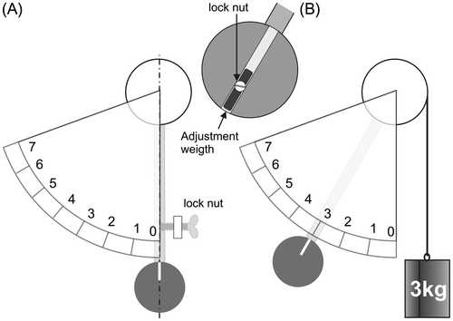
Sinus-balance cycle ergometers can easily be statically calibrated. As in any calibration, the first step consists in checking the zero (Figure (A)). After detaching the belt, the pendulum hangs in vertical position. The position of the force scale is adjusted with the lock nut so that the index on the pendulum weight is aligned with the zero of the scale. The second step consists in the calibration of force: known weights (at least 3 kg) are suspended at the point of belt attachment and the pendulum index must be in front of the corresponding weight on the scale. If necessary the position of the pendulum can be modified by an adjustment weight. The reading of the scale must be careful. As mentioned by Maxwell et al. (Citation1998), a misalignment of the pendulum and scale equivalent to the thickness (2 mm) of the lines on the ergometer’s pendulum resulted in errors of 7.8 (4.6 W) and 0.7% (2.3 W) at power outputs of 58.9 and 353.2 W, respectively.
5.2. “Static” calibration of the weight-basket loaded ergometers
In theory, the value of FB is a FFW overestimation equal to FS(1 − rS/rT). Therefore, the magnitude of this overestimation could theoretically be estimated by measuring the only value of FS. Frictional torque in the pulley axis is another cause of error in FFW. Therefore, the calibration of FFW necessitates the measurements of both FT and FS with force transducers. However, the first step of the calibration procedure consists in verifying the weights of the baskets and the weights. Indeed, the actual weights corresponding to the 1 kilogram weights supplied with the MonarkTM 864 ergometer ranged from 0.950 to 1.050 kg (unpublished personnal data, weighing of fifteen 1-kilogram weigths), i.e. a range of error equal to ±5%. However, this error was probably lower in the study by Gordon, Franklin, Baker, and Davies (Citation2004) on the accuracy of MonarkTM 824E ergometer.
The values of FS and FT were measured with force transducer in a study by MacIntosh, Bryan, Rishaug, & Norris (Citation2001) on the validity of a Wingate test performed on MonarkTM 834 E ergometer. The measured values of FT and FS were, respectively, equal to 95.5 and 6.17% of the weight of the basket, respectively. But, these results were dubious because FT should be higher than FB (FT = FB + FSrS/rT). It was likely that the weights were not verified as this first calibration step was not mentionned in the calibration procedure. Calibration errors of the force tranducers and an excessive frictional torque in the pulley were other possible explanations. Moreover, as mentionned by Franklin, Gordon, Baker, and Davies (Citation2007), the computed brake torque in the study by MacIntosh et al. (Citation2001) was computed from the difference between FT and FS without taking into account the difference in the radii of the pulley for the slack rope and tight belt.
In the first part of an experimental study by Gordon et al. (Citation2004), the flywheel was removed from a MonarkTM 824E cycle ergometer, mounted in a frame, and rotated using a motor connected via a chain drive. The dynamic friction coefficient of the belt-rope was estimated by measuring the values of FT for a given value of FS (9.98 N):
The value of ln (FT/9.98) was computed for different values of the angle of lap of the rope around the flywheel. The slope (0.175) of the linear regression (r2 = 0.9956) between the lap angle and the logarithm of ratio FT/FS was considered as equal to the dynamic coefficient of friction μ. Gordon et al. (Citation2004) computed the value of FT and FS with the theoretical values corresponding to different calibrated basket weight (from 1 to 6 kg) with μ = 0.175 and θ = 10.4 rad. The conclusion of this study was that FB corresponded to a 10.8% overestimation of FTW with a MonarkTM 824 ergometer. However, it was assumed that the experimental value of μ was exact, which was questionable (see Appendix 2). In the second part of their study, Gordon et al. (Citation2004) measured the values of FT and FS with force transducers attached to the brake-rope on both the tight and slack sides while a subject pedaled against different resistances on the same MonarkTM 324 E ergometer (same flywheel and same belt-rope). The second part of this experimental study confirmed that FS was not negligible and, consequently, that FB was an overestimation of FFW. However, the measures of FS were probably not accurate enough for an estimation of the errors in power output during cycling.
In Figure of the study by Franklin et al. (Citation2007), the values of FT and FS measured with force transducers for a 2 kg basket weight was equal to 20 and 0.8 N, respectively. Therefore, FB (19.62 N) was an overestimation of FFW (19.2 N) equal to 0.4 N, i.e. a 2% overestimation. This overestimation was in agreement with the expected overestimation [FS(1 − rS/rT) = 0.44 N] as ratio rS/rT was equal to 0.45. However, the difference between FB and FFW increased with weight. For example, FB was a 14.9% overestimation of FFW for a basket weight equal to 8 kg. But ratio FT/FS (equal to k) should be constant if the values of μ and θ are independent of the basket weight. Consequently, the overestimation of FFW should be independent of basket weight when expressed in fraction of FB:
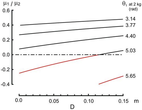
There is no mysterious force acting of the MonarkTM ergometer. How to explain the basket-weight dependence of FFW overestimation in the study by Franklin et al. (Citation2007)? A first explanation is a decrease in β. Indeed, the basket moves down when the weight increases and the tight belt winds around the pulley while the rear rope unwinds. Therefore, θ1 decreases for the belt and θ2 increases for the rope. If μ1 is lower than μ2, the values of β and k decrease. However, such an explanation assumes that μ2 was at least 2-fold higher than μ1 (μ1/μ2 < 0.5; see Appendix 3), which was unlikely as suggested by the measure of the coefficient of friction of the belt-rope on the flywheel of a MonarkTM ergometer in the study by Gordon et al. (Citation2004) (see Appendix 2).
For all the friction-loaded ergometers, the underlying assumption is that there is no external force acting on the belt-rope-pulley system except the frictional force exerted at the flywheel and the force exerted by the basket (FB). The design of the frames of models 824 and 834 was probably the cause of an additional error in FFW. Indeed, the roller chain supplied with these ergometers was too short and the frame of the ergometer pressed on the slight rope (Figure ). Therefore, the FFW was not equal to difference between FT and FS because of the contact of the slack rope on the ergometer frame. This importance of this frictional force due to this contact probably depends on the conditions of the friction of the rope on the frame (steady or varying tension) and on the load, which could explain why the error in FFW was larger with the heavy basket weight in the study by Franklin et al. (Citation2007). One or two links had to be added to the roller chain to avoid this contact for the specimens of this kind of weight-basket loaded ergometers, we used.
5.3. Dynamic calibration
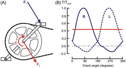
Dynamic calibration takes into account energy losses due to friction in the chain and sprockets in addition to the errors due to the torque regulation mechanism. Dynamic calibration consists of the measurement of the torque necessary to exert on the cycle ergometer to produce the required power. This torque is produced by a motor at different rotational speeds and power input to the ergometer is equal to the product of torque (N m) and angular speed (rad s−1). In theory, the torque should be exerted on the pedal in the same conditions as during cycling exercises, i.e. the same force (intensity and direction) as the force exerted on the pedal at each crank angle during one revolution. In practice, the calibration rig exerts a constant couple on the crank shaft, which alters the validity of the calibration. Indeed, the action of the force exerted on the pedal (F1 in Figure (A)) is equivalent to a force F2 exerted on the crank shaft plus a couple C whose moment is equal to the torque of F1 about crank shaft. Therefore, the effect of F2 on the ball-bearings is not taken into account in dynamic calibration as the calibration rig exerted only a couple equivalent to C. Moreover, the couple exerted by the calibration rig is constant (red line in Figure (B)), whereas there are large variations in the torque exerted on the pedals during one revolution (blue lines in Figure (B)). These variations in torque induce similar variations in the mechanical strains of the roller chain, flywheel sprocket, and bearings. The underlying assumption of dynamic calibration is that energy losses in chain and ball bearing are similar for varying and constant torques. Moreover, dynamic calibration devices are attached to crank axle. Therefore, the losses occurring in the foot-pedal bearing are not taken into account but are considered as small and negligible.
Figure 17. In A decomposition of the force F1 exerted on the pedal into a force F2 exerted on the crank shaft and a couple C; in B comparison of the mean torque (red line) and the torques exerted on the left (blue dashed line, L) and right crank (blue continuous line, R) during a pedal revolution.
5.3.1. Dynamic calibration: Methods
The crankshaft resistance to rotation causes an opposite-direction rotation of the calibration motor which is prevented by its fixation on a frame and/or the ground. The torque exerted by the calibration motor on the crankshaft is equal to the reaction torque exerted by the motor on the frame and/or the ground. In most of the experimental studies on cycle ergometer calibration, the reaction torque has been measured by an arm lever linked to the motor and connected to different force transducer (scale with weights, spring scale, force platform, arm lever with weight, force transducers). The use of these reaction transducers is cost effective as these sensors do not utilize bearings, slip-rings, or any other rotating elements. Moreover, these calibrators are not limited in rotation speed by the torque transducer. Most of the first studies on dynamic calibration of cycle ergometers used reaction-torque measurements (Abbiss, Quod, Levin, Martin, & Laursen, Citation2009; Cumming & Alexander, Citation1968; Gardner et al., Citation2004; Kyle & Caiozzo, Citation1986; Maxwell et al., Citation1998; Wilmore et al., Citation1982; Woods, Day, Withers, Ilsley, & Maxwell, Citation1994).
The calibration can also be carried out with a motor previously calibrated with a Prony brake. First, the current necessary to exert a calibrated torque on the Prony brake is registered for different rotational speeds. Current–torque curves are determined for the usual pedal rate (e.g. current–torque curves corresponding to 40, 60, 80, and 100 rpm). Thereafter, the cycle ergometers are dynamically calibrated by measuring the current necessary for the calibration motor to produce a given power on the cycle ergometer. Thereafter, this current is compared with the current–torque curves previously determined for a given pedal cadence.
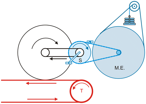
The torque exerted on the crankshaft by the motor can also be directly measured by a torque transducer mounted between motor shaft and crankshaft. For example in the study by Russell and Dale (Citation1986), the rotating torque meter was made of the combination of a spring rotating 90° at 70 N m and a 100 kΩ multiturn potentiometer. Devices measuring the torque generated at the crank axle by means of strain gauges situated between the crank shaft and the chain wheel were described by Atkins and Nicholson (Citation1963) and Atkins and Nünlist (Citation1966). As for the Russel-Dale torque transducer, brass slip rings with brushes were necessary for transmission of the excitation voltage and data. Nowadays, the torque measured by this kind of device can be inductively transmitted at high frequency (500 kHz) to the data recorder as for example with the SRMTM crankset (Schoberer Rad Messtechnik, Jülich, Germany). The measures of torque with SRMTM crankset (Schoberer, Citation1998) is performed by means of strain gauges (2, 4, 8, and 20 depending on the model) mounted between the crank arms and the chain-rings. The accuracy of the SRMTM crankset increases with the number of strain gauges (from 2 to 0.5%, according to the manufacturer). Jones and Passfield (Citation1998) studied the accuracy of the SRMTM transducers by comparing the work performed on a MonarkTM ergometer model 814E (Figure ) and the data of 3 SRMTM transducers [2 models with 20 strain gauges (SRM20sg) and 1 model with 4 strain gauges (SRM4sg)]. The relationship between SRMTM and MonarkTM data was almost perfectly linear and the 95% limits of agreement were ± 1.1 W (±0.3%) for the first SRM20sg, ± 1.8 W ( ± 1.0%) for the second SRM20sg, and ± 2.1 W ( ± 1.8%) for the model SRM4sg. However, the accuracy of the SRMTM transducer was questioned by Gardner et al. (Citation2004) who compared the data collected with 19 SRMTM transducers (models with 4 strain gauges) and a calibration rig. This latter study showed large difference in accuracy between the 19 SRMTM transducers (2.3 ± 4.9%; min 1% max −10.4%). However, when tested during steady-state protocols, the accuracy of SRMTM transducers with 8 strain gauges was higher (difference with a calibration rig <1%) in a more recent study by Abbiss et al. (Citation2009). Several studies have investigated the test–retest reliability of performance measured with SRMTM cranksets. Balmer et al. (Citation2000) and Smith, Davison, Balmer, and Bird (Citation2001) reported standard errors of measurement lower than 2% for power output recorded on the SRMTM crankset in repeated laboratory tests with competitive cyclists. A static calibration procedure for SRMTM crankset has been proposed by Wooles, Robinson, and Keen (Citation2005).
Figure 18. Schematic diagram of the method used in the study by Jones & Passfield (Citation1998) for the comparison of a basket-loaded MonarkTM ergometer (in blue), model 814 (ME) and data of different SRMTM transducers.
In recent years, most of the dynamic calibrations of new cycle ergometers (Balmer et al., Citation2000; Bertucci, Duc, Villerius, & Grappe, Citation2005; Hopker, Myers, Jobson, Bruce, & Passfield, Citation2010; Hurst & Atkins, Citation2006; Kirkland, Coleman, Wiles, & Hopker, Citation2008) or ergometric pedal (Stapelfeldt, Mornieux, Oberheim, Belli, & Gollhofer, Citation2007) were performed by means of SRMTM transducers.
5.3.2. Dynamic calibration: Results
In the study by Cumming and Alexander (Citation1968) carried out on 4 sinus-balance ergometers, the underestimation depended on power output (Figure ). When expressed in absolute value (watts), the underestimation increased with power output. However, the underestimation decreased when it was expressed in percent of power output. In contrast, Kyle and Caiozzo (Citation1986) using a dynamic calibration of a modified MonarkTM sinus-balance ergometer found that the losses increased with power output even when they were expressed in percentages: 2 and 4% for 150 and 300 W, respectively. As the energy loss increased with power output, Kyle and Caiozzo assumed that that energy loss was around 10% beyond 1,000 W. However, the modified MonarkTM ergometer in the study by Kyle and Caiozzo consisted of a standard racing bicycle with derailleur connected to the ergometer flywheel of a von Döbeln braking device. Therefore, it was likely that there was an additional energy loss in the derailleur and that the losses were lower in a real MonarkTM sinus-balance ergometer. In the study by Wilmore et al. (Citation1982), the power output on a friction-loaded cycle ergometer was approximately 10% below the actual values given by dynamic calibration at each power output (Figure ). This result is in agreement with the manufacturer’s handbook for the MonarkTM cycle ergometer that acknowledges a 9% underestimation of the actual power output.
Figure 19. Results of dynamic calibrations of friction-loaded ergometers.
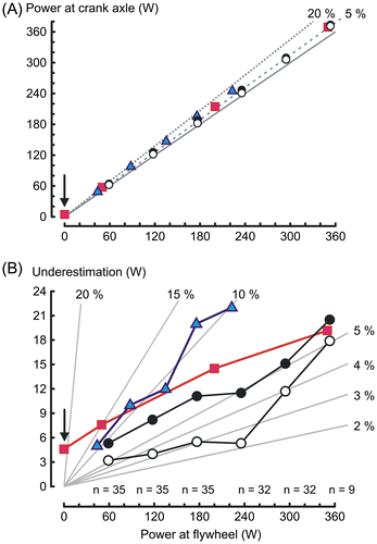
The dynamic calibration of friction-loaded ergometers was compared with the calibrations of air and electromechanically braked cycle ergometers in a study by Maxwell et al. (Citation1998). Dynamic calibration was carried out in old and new MonarkTM ergometer with increasing (black points in Figure ) and decreasing (empty circles in Figure ) power output. Unfortunately, the models of the new and old MonarkTM ergometers were not specified and the numbers of ergometers were different under and beyond 180 W. Nonetheless, this interesting study indicated that the underestimation was lower than 9% and was slightly lower with decreasing loads than with increasing loads (Figure ). This hysteresis phenomenon can probably be explained by an increase in the coefficient of kinetic friction with the increase in temperature or the belt and/or flywheel (Kauffman & Vondracek, Citation2005).
As mentioned above, Jones and Passfield (Citation1998) compared the work performed on a MonarkTM ergometer model 814E (Figure ) and the data of SRMTM transducers. As the crankset of MonarkTM ergometer model 814E was a single-unit piece, dynamic calibration cannot be achieved without a special adapter connecting the shaft of calibrator rig to the shaft of the ergometer. In the study by Jones & Passfield, the dynamic calibration rig consisted of a modified friction-braked MonarkTM ergometer driven by a motorized treadmill (Figure ). Thirteen braking loads were used at a pedal rate of 90 rpm, which corresponded to power outputs ranging from 90 to 625 W. At each load, the difference between power output and SRMTM data was very low (see above): the 95% limits of agreement computed from the residuals of the linear regression were inferior or equal to ±2.1 W.
5.4. Physiological calibration
Physiological calibration can be achieved by comparing oxygen uptake during exercises performed with a cycle ergometer and another ergometer dynamically calibrated. It is assumed that the individual adaptations are similar at the same power output for any cycle ergometers and that any difference in oxygen uptake would be the expression of inaccuracy in displayed power output. For example the comparison can concern either the oxygen uptake for a given power output or the slope of the relationship between power and oxygen uptake (ml O2 min−1 W−1). Assuming an energy equivalent for oxygen consumption (about 20.3 J ml O2−1 for a respiratory quotient between 0.85 and 0.9), the delta efficiency (delta efficiency = delta power/delta energy consumption) can also be compared.
5.4.1. Comparison of physiological adaptations within the same laboratory
Brue et al. (Citation1985) validated their new friction-loaded ergometer by determining the relationship between power and oxygen uptake measured during exercises on an ErgomécaTM ergometer and found the same slope (11.6 ml O2 min−1 W−1) as previously collected on a Siemens-ElemaTM or a MonarkTM ergometer in their laboratory. Guiraud et al. (Citation2010) compared the oxygen uptake during exercises performed by five subjects on a dynamically calibrated ergometer and different cycle ergometers. The energy cost of cycling was equivalent to 13 ml O2 min−1 W−1 (delta efficiency = 0.228) for a MonarkTM 824E and 12.5 ml O2 min−1 W−1 for an ErgomécaTM (delta efficiency = 0.237). The oxygen uptake with the ErgomécaTM and MonarkTM were higher than the oxygen uptake for the same power output with the calibrated ergometer, which indicated that power output were underestimated (mean −5 W for the ErgomécaTM and −15 W for MonarkTM 824E).
The accuracy of physiological calibration depends not only on the errors of power output with both ergometers (calibrated and uncalibrated ergometers) but also on errors in the measurement of oxygen uptake during the exercise protocols performed with both ergometers. Therefore, the accuracy of physiological calibration should be significantly lower when compared with dynamic calibration of a single ergometer.
5.4.2. Comparisons with data in the literature
Physiological calibration can also be achieved by comparing the oxygen uptake measured during exercises performed with a given cycle ergometer with previous data in the literature. For example, it is possible to compare the oxygen uptake measured with a friction-loaded ergometer with the oxygen uptake corresponding to a given power output in the nomogram presented by Åstrand (Citation1960) for exercises performed with a von Döbeln ergometer or a Krogh ergometer. In this nomogram, the cycling energy cost was equal to 13.1 ml O2 min−1 W−1 for power output between 300 and 1,500 kgm min−1 (i.e. between W for 1 kgm min = 6.11 W), i.e. the same energy cost as in the study by Guiraud et al. (Citation2010) for a MonarkTM 824E. The cycling energy cost can also be compared with data obtained with calibrated ergometers in the literature. For example, in the study by McDaniel, Durstine, Hand, and Martin (Citation2002) the delta efficiency during cycling exercises on an ergometer calibrated with a SRMTM crankset was equal to 0.247, i.e. an energy cost of cycling equal to 11.9 ml O2 min−1 W−1. Similarly, the regression line between power output and metabolism in Figure (C) of the review on cycling efficiency by Ettema & Lorås (Citation2009) corresponded to delta efficiency equal to 0.250, i.e. energy cost equal to 11.8 ml O2 min−1 W−1. The 9% higher energy cost of cycling on a MonarkTM 824E ergometer in the study by Guiraud et al. (Citation2010) when compared with either McDaniel et al. (Citation2002) or Ettema & Lorås (Citation2009) data suggested a 9% underestimation of power output with this kind of ergometers in agreement with the manufacturer’s handbook for the MonarkTM cycle ergometers.
However, the comparison of physiological data with previous data in the literature must be cautious. For example, a lower cycling energy cost was found for a friction-braked ergometer, in the study on the dynamic calibration of different cycle ergometers by Wilmore et al. (Citation1982). In this latter study, physiological variables were also measured in 10 subjects during incremental exercises. When power outputs were corrected according to the result of the dynamic calibration, the energy cost of cycling with a friction-loaded ergometer was equal to 10.9 ml O2 min−1 W−1 in agreement with the cycling energy cost for the ACSM (10.8 ml O2 min−1 W−1) (American Journal of Sports Medicine, Citation2007). Therefore, cycling energy cost was 20.4% higher in the study by Guiraud et al. (Citation2010), when compared with Wilmore data. Underestimation of power output is not the only cause of differences in cycling energy cost between studies. These differences can also be explained by differences in protocols, subjects, and power range. First, the relationship between power-output and oxygen uptake is not perfectly linear: the slope of the relationship is lower at low power outputs. For example, cycling energy cost was 11.76 ml O2 min−1 W−1 between 300 and 900 kgm min−1 instead of 13.1 ml O2 min−1 W−1 for power output between 300 and 1,500 kgm min−1 in Åstrand nomogram (Citation1960). This low value of cycling energy cost at low power outputs could explain the results in the study by Wilmore et al. (Citation1982) obtained for exercises performed between 49 and 147 W that corresponded to heart rates between 89 ± 14 and 131 ± 21 beats min−1, only. Secondly, cycling efficiency depends on the subjects and probably on the percentage of type-I muscle fibers (Coyle, Sidossis, Horowitz, & Beltz, Citation1992) at low pedal rates. Thirdly, cycling efficiency depends on pedal rate (Ettema & Lorås, Citation2009), which could partly explain the high energy cost in Astrand nomogram corresponding to cycling exercises performed at 50 rpm. Differences in cycling energy costs can also be due to errors of measurement. These errors can be subdivided in bias errors (systematic errors) and random errors. Systematic error or bias refers to deviations that are not due to chance. Bias occurs with measuring devices that are not properly calibrated so that they consistently overestimate or underestimate the measurements. The bias error of the oxygen uptake measurements with the calibrated ergometer and uncalibrated ergometer can be similar (under or overestimation) and the effect of bias upon the comparison of cycling energy cost and/or delta efficiency is diminished or canceled. When performed in the same laboratory with the same oxygen uptake device within the same period, bias are similar and their effects on the difference in cycling energy cost are canceled. On the contrary, this effect is amplified in the case of bias with opposite directions when oxygen uptake is overestimated in a laboratory and underestimated in the other laboratory.
6. Maintenance of friction-loaded ergometers
The study by Maxwell et al. (Citation1998) demonstrated the importance of maintenance. For example, the accuracy of a MonarkTM ergometer that was equal to 86% before servicing, reached 93% after cleaning and lubrication of the bearings and roller chain, optimization of the chain tension, tightening of the cones, and readjustment of the chain guard that rubbed against the chain. The different parts of a cycle ergometer that must be maintained are presented in Figure . However, maintenance performed poorly can have the opposite effect to that intended and cause an increase in frictional losses. Fortunately, this maintenance can be achieved with the help of an expert mechanic in competitive cycling. Indeed, the aims of the maintenance of cycle ergometers and race cycles are similar: to decrease energy loss.
Figure 20. Parts of a cycle ergometer that must be maintained (explanations in text); 7, chain adjuster bolt, lateral view.
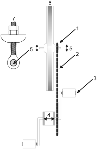
First, the chain guard must be removed. The chain (Figure (Part-2)) and cones (Figure (Part-4)) can be attacked by rust. Indeed, sweat may have infiltrated between the frame and the chain guard when ergometers have been frequently used for intense and prolonged exercises. Freewheeling sprocket (Figure (Part-1)) and chain must be checked and eventually changed. Indeed, chain “stretches” because of wearing away of the metal where the link pins rotate as the chain links flex and straighten. A “stretched” chain no longer matches the original pitch of the sprocket. Thereafter, the sprocket, in turn, increases its pitch to match the worn chain. Similarly, a worn sprocket induces a wearing of the chain. Therefore, it is better to change chain and freewheeling sprocket simultaneously. The wear of the chain and the sprocket is faster when they are not parallel. Abnormal wear of the chain and chainwheel is also observed when chain play is about 20 mm in the middle of its free length. On the other hand, the chain should have a minimum play of 5 mm. The chain adjuster bolts (Figure (Part-7)) enable the adjustment of the chain play between 5 and 20 mm and the parallelism of flywheel sprocket and the chain. Hub bolts (Figure (Part-5)) are tightened after these adjustments.
Friction in the pedal bearings (Figure (Part-3)) is generally considered as negligible, which is debatable. When necessary, it is easier to remove the pedals for replacement than to service the pedal bearings. The axles of the pedals screw into the cranks. It is important to remember that pedal threads are different from right side and left side. Therefore, pedals are generally stamped “R” and “L” for right and left. The right side pedal has a right-hand thread (installs clockwise, removes counterclockwise), whereas the left side pedal has a left-hand thread (installs counterclockwise, removes clockwise).
The crankset bearing should be checked at regular intervals to see that there is no play in the bearing. Whatever, the crankset system, the tightening of the cones (Figure (Part-4)) must be adequate, which requires minimal expertise. Many ergometer crankset consist of a one-piece crank and two cones. A one-piece crank consists of a single steel forging which constitutes the left crank, axle, and right crank in a single piece of steel. The left side cone of the bottom bracket has a left thread, and uses a locknut and keyed washer to secure the adjustment. The right side cone has a right thread, and secures the chainwheel to the crank. This one-piece crank set is difficult to assemble because of the loose balls.
Lubrication of the roller chain and flywheel sprocket is carried out after their cleaning. The bearing in the flywheel and crankset are lifetime greased and required normally no maintenance, unless they need to be replaced. The belt should be regularly checked and replaced if it looks worn. The brake belt contact with the flywheel (Figure (Part-6)) can be cleaned with a fine sand paper to remove dust and eventually attenuate small grooves in the circumference of aluminum flywheels. This procedure is made easier if somebody pedals at very slow cadence.
7. Future of the friction-loaded cycle ergometer
The current friction-loaded cycle ergometers seem to be designed to be attractive and secure but not to be accurate. The guards that limit the risks of accidents due to moving flywheel and chain are not designed to be easily removed for regular checking and maintenance of the ergometers. The guard of the associated electronic devices measuring pedal cadence and hear rate masks the pulleys, which, for example, does not facilitate the checking of the tension of the ribbons in the basket-loaded ergometer (Figure ). The maintenance is more difficult with the one piece-cranks than with the usual cup-and-cones or cartridge bottom brackets.
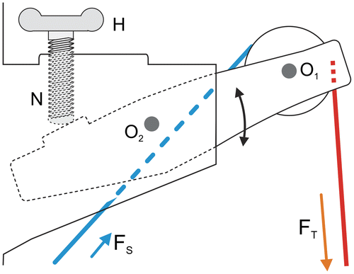
It can be hoped that a friction-loaded ergometer will be designed specifically for medical and physiological studies, i.e. designed for accuracy, maintenance, and calibration. First, one-piece cranks should be replaced with bottom brackets which are easier to service, enable the change of crank length when small people are tested and do not require an adapter for dynamic calibration. Secondly, torque setting can be improved by a mechanism that enables the adjustment of belt tension by a change in the distance between pulley and flywheel shafts (Figure ). Therefore, the pulley pressing on the slack belt in the sinus-balance ergometer (Figure ) can be suppressed and the error of FS due to this external force disappears. Similarly, the ajdustment of the belt tension of the weight-basket loaded ergometers will be easier and even possible during exercise without interruption.
Figure 21. Example of a mechanism enabling the adjustment of the belt tension by a change in distance between the axes of the pulley (O1) and the flywheel; O2, axle of the mechanism; H, handle; N, locking nut.
For the basket-loaded ergometers, the error in FFW decreases with FS (Equation 9). The value of FS can be diminished by an increase in θ and/or an increase in μ. An increase in θ can be achieved by replacing the belt-rope with a rope with three turns around the flywheel (Figure (D)). An increase in the apparent friction coefficient μ could be achieved by replacing the belt with a “V-belt”, for example by digging small grooves in the circumference of the flywheel. Another way to decrease the error in FFW is to increase ratio rS/rT (Equation 9) by adding layers on the small pulley or by replacing both pulleys. For example, the error is 57% higher with rS/rT equal to 0.45 instead of 0.65.
About 20 years ago, we tried a basket-loaded braking mechanism (Figure ) which consisted of a belt made of a low-friction ribbon (TeflonTM, μ1 between 0.05 and 0.2) in series with the usual belt (μ2 between 0.15 and 0.2). The radii of the pulleys were identical for FT and FS (rS = rT). Therefore, at equilibrium, FB was equal to FFW according to equation 9 (FFW = FB − FS (1 − rS/rT) = FB).
Figure 22. Braking mechanism consisting of a friction belt made of two belts in series; in red, belt with low friction coefficient (μ1); in blue, belt with high friction-coefficient (μ2).
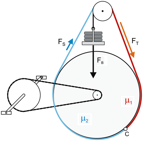
Let θ1 + 2 = θ1 + θ2 = constant.
where the effective friction coefficient μ1 + 2 is equal to [μ2 − α(μ2 − μ1)].
When FFW was higher than FB, the basket moved up, α increased and μ1+2 decreased. Therefore, FFW decreased as the effective friction coefficient decreased. Inversely, when FFW was lower than FB, the basket moved down. Therefore, α, μ1 + 2 and FFW increased. Unfortunately, the pulley largely oscillated probably because of an inadequate choice of μ1, μ2, θ1, θ2, and compliance of the belt. It would be interesting to repeat this trial with new material and different values of θ1 and θ2.
In theory, force-speed tests on friction-loaded ergometers could be used to estimate the muscular strength and contractility. Unfortunately, the values of V0 and F0 depend not only on muscle properties but also on crank length. Moreover, the time to Vpeak during an all-out sprint on a cycle ergometer is longer in children because of the flywheel inertia. Instead of changing the flywheel, it would be easier to change the ratio between chainwheel and sprocket (52/14) simultaneously with the change of crank length. Indeed, the kinetic energy of the flywheel depends on the square of its angular speed and the kinetic energy at Vpeak is 1.94 times less if the chainwheel-sprocket ratio is 48/18 instead of 52/14. The ergometer adaptation to children testing would consist in replacing the adult crankset with shorter cranks and a chainwheel with 48 teeth. A two-sprocket freewheel (14 and 18 teeth) would be mounted on the flywheel. In a first approximation, the chain length is similar if the number of teeth of chainwheel + sprocket is the same (52 + 14 = 48 + 18 = 66). The chain wheel and the freewheel sprocket would be manually swapped after loosening the chain and changing the crankset. The tension of the chain would be adjusted without a derailleur but with the chain adjuster bolts. The power output corresponding to a given resistance must be divided by 1.39 to take into account the change in the chainwheel-sprocket ratio. On the other hand, the optimal resistance for a Wingate test must be multiplied by 1.39, that is, 10.4% body mass instead of 7.5% in children.
The measurement of PPcorr according to Lakomy’s method and the assessment of the torque–speed relationship during all-out sprint are based on the computation of flywheel acceleration. The inertia of the flywheel is generally measured according to Lakomy’s method, that is, the measurement of the deceleration of the flywheel rotating against different braking force (FFW). The underlying assumption is that FFW and FB are equal, which is not exact. Therefore, the errors in PPcorr and torque–speed relationship are the consequence of errors of FFW not only during the all-out sprints but also during the determination of flywheel inertia. The flywheels should be supplied with the value of its inertia calibrated by the ergometer manufacturers.
The cycle ergometers should be supplied with a digital high-accuracy speed transducer mounted on the flywheel and connectable to external computing devices. Such transducers would enable not only an accurate measurement of flywheel acceleration during all-out sprints but also the computation of the actual power output during constant-power protocols. Indeed, variability in pedal rate is the third cause of errors in power output with errors in brake torque and energy losses in chain and ball bearings.
Cover image
Source: Authors.
Additional information
Funding
Notes on contributors
Henry Vandewalle
Henry Vandewalle, PhD, is a medical doctor. Most of his research papers were dedicated to the measurement of maximal anaerobic power and capacity on a cycle ergometer, which was the topic of his doctoral thesis in Biomechanics and Physiology, presented in 1986. In the next 10 years, he proposed different protocols of determination of torque–velocity relationship from data collected during a single all-out sprint on a cycle ergometer and studied the effect of fatigue on the parameters of this relationship.
Tarak Driss
Tarak Driss is an associate professor and the Dean of the Faculty of Sports Sciences (University of Paris Ouest Nanterre La Défense). He completed his MSc and PhD in the field of Exercise Physiology and Biomechanics at Paris VI University. Currently, he studies the human physical performance, and the mechanisms and adaptations to exercise and training particularly in the areas of cycling, vertical jump, and muscle isometric contraction.
References
- Abbiss, C. R., Quod, M. J., Levin, G., Martin, D. T., & Laursen, P. B. (2009). Accuracy of the Velotron ergometer and SRM power meter. International Journal of Sports Medicine, 30, 107–112.10.1055/s-0028-1103285
- Adamson, G. T., & Whitney, R. J. (1971). Critical appraisal of jumping as a measure of human power. In J. Vredenbregt & J. Wartenweiler (Eds.), Medicine and sport 6: Biomechanics II (pp. 208–211). Basel: Karger.
- Amar, J. (1909). Le rendement de la machine humaine [Mechanical efficiency of the human machine] (doctoral thesis) (in French). Baillière, Paris.
- American College of Sports Medicine. (2007). In S. Glass & B. Dwyer (Eds.), ACSM’s metabolic calculations handbook (p. 111). Baltimore, MD: Lippincott Williams & Wilkins.
- Åstrand, I. (1960). Aerobic work capacity in men and women with special reference to age. Acta Physiologica Scandinavica, 49( supplementum 169), 1–92.
- Atkins, A. R., & Nicholson, J. D. (1963). An accurate constant-work ergometer. Journal of Applied Physiology, 18, 203–208.
- Atkins, A. R., & Nünlist, A. (1966). A precision constant work-rate ergometer. Journal of Applied Physiology, 21, 1427–1430.
- Ayalon, A., Inbar O., & Bar-Or O. (1974). Relationship among measurements of explosive strength and anaerobic power. In R. C. Nelson & C. A. Morehouse (Eds.), International series on sport sciences (Vol. 1, Biomechanics V, pp. 572–577). Baltimore, MD: University Park Press.
- Balmer, J., Davison, R. C., Coleman, D. A., & Bird, S. R. (2000). The validity of power output recorded during exercise performance tests using a Kingcycle air-braked cycle ergometer when compared with an SRM powermeter. International Journal of Sports Medicine, 21, 195–199.10.1055/s-2000-9466
- Bar-Or, O. (1978). A new anaerobic capacity test. Characteristics and applications. In Communication to the 21st World Congress in Sport Medicine. Brasilia.
- Bar-Or, O. (1987). The Wingate anaerobic test: An update on methodology, reliability and validity. Sports Medicine, 4, 381–394.10.2165/00007256-198704060-00001
- Bassett, Jr. D. R. (1989). Correcting the Wingate test for changes in kinetic energy of the Ergometer flywheel. International Journal of Sports Medicine, 10, 446–449.10.1055/s-2007-1024941
- Beaumont, W. W. (1889). Friction-brake dynamometers. Minutes of proceedings of the institution of civil engineers, 95, 1–77.
- Bedu, M., Fellmann, N., Spielvogel, H., Falgairette, G., Van Praagh, E., & Coudert, J. (1991). Force-velocity and 30s Wingate test in boys at high and low altitudes. Journal of Applied Physiology, 70, 1031–1037.
- Benedict, F. G., & Cady, W. G. (1912). A bicycle ergometer with an electric brake (Issue 167, p. 44). Carnegie Institution of Washington. New York, NY: Isaac H Blanchard..
- Benedict, F. G., & Carpenter, T. M. (1909). The influence of muscular and mental work on metabolism and the efficiency of the human body as a machine (Bulletin No. 208). US Department of Agriculture, Office of Experimental Stations.
- Bertucci, W., Duc, S., Villerius, V., & Grappe, F. (2005). Validity and reliability of the axiom powertrain cycle ergometer when compared with an SRM powermeter. International Journal of Sports Medicine, 26, 59–65.10.1055/s-2004-817855
- Bouny, E. (1896a). Mesure du travail dépensé dans l’emploi de la bicyclette, Note de M Bouny présenté par M Marey [Measure of the work output during the use of a bicycle, note by Mr Bouny presented by Mr Marey]. Comptes-rendus des séances de l’Académie des Sciences, 122, 1391–1396.
- Bouny E. (1896b). Contrôle de la pédale dynamométrique de bicyclette, Note de M Bouny présenté par M Marey [Control of the dynamometric pedal of a bicycle, note by Mr Bouny presented by Mr Marey]. Comptes-rendus des séances de l’Académie des Sciences, 122, 1528–1530.
- Brue, F., Melin, B., & Lamande, J. P. (1985). Détermination de l’aptitude différentielle aérobie-anaérobie sur un nouveau type de cyclo-ergomètre [Determination of the specific ability in aerobic and anaerobic exercises by means of a new cycle ergometer] (in French). Cinésiologie, 24, 341–345.
- Brue, F., Melin, B., Lamande, J. P., & Philippe, Y. (1983, September). The direct determination maximal aerobic and anaerobic powers using a new mechanical cycle ergometer. In Proceedings of the 5th Meeting of RSG 4 North Atlantic Treaty Organisation, (pp. 11–15, 44), Brussels, Belgium.
- Carpentier, J. A. M. L. (1880). Rapport fait par M Ed. Collignon sur les Freins dynamométriques de M Carpentier et M Marcel Desprez [Report presented by Mr E. Collignon on the dynamometric brakes of Mr J. Carpentier and Mr M. Desprez] (in French). Bulletin de la société d’encouragement pour l’industrie nationale, VII, 445–450.
- Coyle, E. F., Sidossis, L. S., Horowitz, J. F., & Beltz, J. D. (1992). Cycling efficiency is related to the percentage of type I muscle fibers. Medicine and Science in Sports and Exercise, 24, 782–788.
- Cumming, G. R., & Alexander, W. D. (1968). The calibration of bicycle ergometers. Canadian Journal of Physiology and Pharmacology, 46, 917–919.10.1139/y68-145
- Dickinson, S. (1928). The dynamics of bicycle pedalliug. Proceedings of the Royal Society B: Biological Sciences, 103, 225–233.10.1098/rspb.1928.0037
- Dickinson, S. (1929). The efficiency of bicycle-pedalling, as affected by speed and load. The Journal of Physiology, 67, 242–255.10.1113/jphysiol.1929.sp002565
- Dotan, R., & Bar-Or, O. (1983). Load optimization for the wingate anaerobic test. European Journal of Applied Physiology and Occupational Physiology, 51, 409–417.10.1007/BF00429077
- Driss, T., & Vandewalle, H. (2013). The measurement of maximal (anaerobic) power output on a cycle ergometer: A critical review. BioMed Research International, 2013(1), 1–40.10.1155/2013/589361
- Driss, T., Vandewalle, H., Le Chevalier, J. M., & Monod, H. (2002). Force-velocity relationship on a cycle ergometer and knee-extensor strength indices. Canadian Journal of Applied Physiology, 27, 250–262.10.1139/h02-015
- Ettema, G., & Lorås, H. W. (2009). Efficiency in cycling: A review. European Journal of Applied Physiology, 106, 1–14.10.1007/s00421-009-1008-7
- Fenn, W. O., & Marsh, B. S. (1935). Muscular force at different speeds of shortening. The Journal of Physiology, 85, 277–297.10.1113/jphysiol.1935.sp003318
- Fleisch, A. (1950). Ergostat à puissances constantes et multiples [Ergometer with constant and multiple power outputs] (in French). Helvetica Medica Acta series A, 17, 47–58.
- Franklin, K. L., Gordon, R. S., Baker, J. S., & Davies, B. (2007). Accurate assessment of work done and power during a wingate anaerobic test. Applied Physiology, Nutrition and Metabolism, 32, 225–232.10.1139/h06-103
- Gaertner, G. (1887). Über die therapeutische Verwendung der Muskelarbeit und einen neuen Apparat zu ihrer Dosierung [On the therapeutic use of muscular work and a new device for its dosage] (in German). Wiener medizinische Zeitung, 32, 607–621.
- Gardner, A. S., Stephens, S., Martin, D. T., Lawton, E., Lee, H., & Jenkins, D. (2004). Accuracy of SRM and power tap power monitoring systems for bicycling. Medicine and Science in Sports and Exercise, 36, 1252–1258.10.1249/01.MSS.0000132380.21785.03
- Gordon, R. S., Franklin, K. L., Baker, J. S., & Davies, B. (2004). Accurate assessment of the brake torque on a rope-braked cycle ergometer. Sports Engineering, 7, 131–138.10.1007/BF02844051
- Granier, P., Mercier, B., Mercier, J., Anselme, F., & Prefaut, C. (1995). Aerobic and anaerobic contribution to Wingate test performance in sprint and middle distance runners. European Journal of Applied Physiology and Occupational Physiology, 70, 58–65.10.1007/BF00601809
- Guiraud, T., Léger, L., Long, A., Thébault, N., Tremblay, J., & Passelergue, P. (2010). Vo2 requirement at different displayed power outputs on five cycle ergometer models: A preliminary study. British Journal of Sports Medicine, 44, 449–454.10.1136/bjsm.2007.044826
- Harrison, J. Y. (1967). A constant-torque brake for use in bicycle and other ergometers. Journal of Applied Physiology, 23, 989–993.
- Hautier, C. A., Linossier, M. T., Belli, A., Lacour, J. R., & Arsac, L. M. (1996). Optimal velocity for maximal power production in non-isokinetic cycling is related to muscle fibre type composition. European Journal of Applied Physiology and Occupational Physiology, 74, 114–118.10.1007/BF00376503
- Hill, A. V. (1938). The heat of shortening and the dynamic constants of muscle. Proceedings of the Royal Society B: Biological Sciences, 126, 136–195.10.1098/rspb.1938.0050
- Hollmann, W., & Prinz, P. (1991). On the History of Spiroergometry. Computerized Cardiopulmonary Exercise Testing, 1991, 3–17.10.1007/978-3-642-85404-0
- Holmgren, A., & Mattsson, K. H. (1954). A new ergometer with constant work load at varying pedal rate. Scandinavian Journal of Laboratory and Clinical Investigation, 6, 136–140.
- Holzer, W., & Kalinka, M. (1935). Über ein einfaches Fahrradergometer und dessen Eichung [On a simple cycle ergometer and its calibration] (in German). Arbeitsphysiologie, 8, 778–782.
- Hopker, J., Myers, S., Jobson, S. A., Bruce, W., & Passfield, L. (2010). Validity and reliability of the Wattbike cycle ergometer. International Journal of Sports Medicine, 31, 731–736.10.1055/s-0030-1261968
- Hurst, H. T., & Atkins, S. (2006). Power output of field-based downhill mountain biking. Journal of Sports Sciences, 24, 1047–1053.10.1080/02640410500431997
- Inbar, O., Dotan, R., Trousil, T., & Dvir, Z. (1983). The effect of bicycle crank-length variation upon power performance. Ergonomics, 26, 1139–1146.10.1080/00140138308963449
- James, D. V. B., Wood, D. M., Maberly, T. C. B., & Croix, M. D. S. (2007). Optimized versus corrected peak power during friction-braked cycle ergometry in males and females. Journal of Sports Sciences, 25, 859–867.10.1080/02640410600907904
- Jervis-Smith, F. J. (1915). Dynamometers; edited and amplified by C. V. Boys (p. 267). London: Constable.
- Jones, S., & Passfield, L. (1998). The dynamic calibration of bicycle power measuring cranks. In S. J. Haake (Ed.), The engineering of sports (pp. 265–274). Oxford: Blackwell Science.
- Katch, V., Weltman, A., & Traeger, L. (1976). All-out versus a steady paced cycling strategy for maximal work output of short duration. Research Quarterly of the American Association for Health, Physical Education and Recreation, 47, 164–168.
- Katch, V., Weltman, A., Martin, R., & Gray, L. (1977). Optimal test characteristics for maximal anaerobic work on the bicycle ergometer. Research quarterly, 48, 319–327.
- Kauffman, P., & Vondracek, M. (2005). The effect surface temperature has on kinetic friction. The Physics Teacher, 43, 173–175.10.1119/1.1869429
- Kelso, L. E. A., Hellebrandt, F. A., & Madison, W. (1933). The recording electrodynamic brake cycle ergometer. Journal of Laboratory and Clinical Medicine, 19, 1105–1113.
- Kirkland, A., Coleman, D., Wiles, J. D., & Hopker, J. (2008). Validity and reliability of the Ergomo®pro powermeter. International Journal of Sports Medicine, 29, 913–916.10.1055/s-2008-1038621
- Krogh, A. (1913). A bicycle ergometer and respiration apparatus for the experimental study of muscular work. Skandinavisches Archiv Für Physiologie, 30, 375–394.10.1111/apha.1913.30.issue-3
- Kyle, C. R., & Caiozzo, V. J. (1986). Experiments in human ergometry as applied to the design of human powered vehicles. International Journal of Sport Biomechanics, 2, 6–19.
- Lakomy, H. K. A. (1986). Measurement of work and power output using friction-loaded cycle ergometers. Ergonomics, 29, 509–517.10.1080/00140138608968287
- Lakomy, K. (1985). Effect of load on corrected peak power output generated on friction loaded cycle ergometers. Journal of Sports Sciences, 3, 240, Abstract.
- Lanooy, C., & Bonjer, F. H. (1956). A hyperbolic ergometer for cycling and cranking. Journal of Applied Physiology, 9, 499–500.
- Macintosh, B. R., Bryan, S. N., Rishaug, P., & Norris, S. R. (2001). Evaluation of the Monark Wingate ergometer by direct measurement of resistance and velocity. Canadian Journal of Applied Physiology, 26, 543–558.10.1139/h01-030
- Marks, L. S. (1951). The mechanical engineers handbook. New York, NY: McGraw-Hill.
- Martin, J. C., & Spirduso, W. W. (2001). Determinants of maximal cycling power: Crank length, pedaling rate and pedal speed. European Journal of Applied Physiology, 84, 413–418.10.1007/s004210100400
- Martin, J. C., Malina, R. M., & Spirduso, W. W. (2002). Effects of crank length on maximal cycling power and optimal pedaling rate of boys aged 8–11 years. European Journal of Applied Physiology, 86, 215–217.10.1007/s00421-001-0525-9
- Martin, J. C., Wagner, B. M., & Coyle, E. F. (1997). Inertial-load method determines maximal cycling power in a single exercise bout. Medicine and Science in Sports and Exercise, 29, 1505–1512.10.1097/00005768-199711000-00018
- Maxwell, B. F., Withers, R. T., Ilsley, A. H., Wakim, M. J., Woods, G. F., & Day, L. (1998). Dynamic calibration of mechanically, air- and electromagnetically braked cycle ergometers. European Journal of Applied Physiology, 78, 346–352.10.1007/s004210050430
- McDaniel, J., Durstine, J. L., Hand, G. A., & Martin, J. C. (2002). Determinants of metabolic cost during submaximal cycling. Journal of Applied Physiology, 93, 823–828.10.1152/japplphysiol.00982.2001
- Mellerowicz, H. (1962). Ergometrie (p. 254). München-Berlin: Urban & Schwarzenberg.
- Nakamura, Y., Mutoh, Y., & Miyashita, M. (1985). Determination of the peak power output during maximal brief pedalling bouts. Journal of Sports Sciences, 3, 181–187.10.1080/02640418508729750
- Pearson, S. J., Cobbold, M., Orrell, R. W., & Harridge, S. D. R. (2006). Power output and muscle myosin heavy chain composition in young and elderly men. Medicine and Science in Sports and Exercise, 38, 1601–1607.10.1249/01.mss.0000227638.75983.9d
- Pérès, G., Vandewalle, H., & Monod, H. (1981). Aspect particulier de la relation charge-vitesse lors du pédalage sur cycloergometre [Specific pattern of the force–velocity relationship during cycling on a cycle ergometer] (in French). Journal de Physiologie, 77, 10A.
- Poncelet, J. V. (1876). Cours de mécanique appliquée aux machines, 2ème partie [Lectures on mechanics applied to machines, part 2] (in French) (p. 321). Paris: Gauthiers-Villars.
- Ratel, S., Omari, A., Duché P., Bedu, M., & Coudert, J. (1996, May). Cycle ergometer flywheel inertia cannot explain the difference in mechanical anaerobic power between children and adults. In Proceedings of the 1st Annual Congress of European College of Sport Science (pp. 70–71), Nice.
- Russell, J. C., & Dale, J. D. (1986). Dynamic torquemeter calibration of bicycle ergometers. Journal of Applied Physiology, 61, 1217–1220.
- Sargeant, A. J., Hoinville, E., & Young, A. (1981). Maximum leg force and power output during short-termdynamic exercise. Journal of Applied Physiology Respiratory Environmental and Exercise Physiology, 51, 1175–1182.
- Schoberer, U. (1998). Operating Instructions: SRM Training System. Julich: SRM.
- Seck, D., Vandewalle, H., & Monod, H. (1991). Puissance maximale sur ergocycle et délai d'atteinte du pic de vitesse chez l'enfant et l'adulte [Maximal power on a cycle ergometer and delay to peak velocity in children and adults] (in French). Science & Sports, 6, 253–254.10.1016/S0765-1597(05)80168-6
- Seck, D., Vandewalle, H., Decrops, N., & Monod, H. (1995). Maximal power and torque velocity relationship on a cycle ergometer during the acceleration phase of a single all-out exercise. European Journal of Applied Physiology and Occupational Physiology, 70, 161–168.10.1007/BF00361544
- Smith, M. F., Davison, R. C., Balmer, J., & Bird, S. R. (2001). Reliability of mean power recorded during indoor and outdoor self-paced 40 km cycling time-trials. International Journal of Sports Medicine, 22, 270–274.10.1055/s-2001-13813
- Smith, P. M., Price, M. J., Davison, R. C., Scott, D., & Balmer, J. (2007). Reproducibility of power production during sprint arm ergometry. Journal of Strength Conditioning Research, 21, 1315–1319.
- Stapelfeldt, B., Mornieux, G., Oberheim, R., Belli, A., & Gollhofer, A. (2007). Development and evaluation of a new bicycle instrument for measurements of pedal forces and power output in cycling. International Journal of Sports Medicine, 28, 326–332.10.1055/s-2006-924352
- Tuttle, W. W., & Wendler, A. J. (1945). The construction, calibration and use of an alternating current electrodynamic brake bicyle ergometer. Journal of Laboratory and Clinical Medicine, 30, 173–183.
- Van Praagh, E., Fellmann, N., Bedu, M., Falgairette, G., & Coudert, J. (1990). Gender difference in the relationship of anaerobic power output to body composition in children. Pediatric Exercise Science, 70, 1031–1037.
- Van Praagh, E., Bedu, M., Roddier, P., & Coudert, J. (1992). A simple calibration method for mechanically braked cycle ergometers. International Journal of Sports Medicine, 13, 27–30.10.1055/s-2007-1021229
- Vandewalle, H., Heller, J., Pérès, G., & Monod, H. (1985). Effet de la longueur des manivelles sur la puissance maximale et la relation force-vitesse sur ergocycle [Effect of crank length on maximal power and the force–velocity-relationship on a cycle ergometer] (in French). Journal de Physiologie, 80, 5A–6A.
- Vandewalle, H., Pérès, G., Heller, J., & Monod, H. (1985). All out anaerobic capacity tests on cycle ergometers. European Journal of Applied Physiology and Occupational Physiology, 54, 222–229.10.1007/BF02335934
- Vandewalle, H., Pérès, G., & Monod, H. (1983). Relation force-vitesse lors d’exercices cycliques réalisés avec les membres supérieurs [Force–velocity relationship during cyclic exercises performed with the upper limbs] (in French). Motricité Humaine, 2, 22–25.
- Vandewalle, H., Peres, G., Heller, J., Panel, J., & Monod, H. (1987). Force-velocity relationship and maximal power on a cycle ergometer. European Journal of Applied Physiology and Occupational Physiology, 56, 650–656.10.1007/BF00424805
- Vandewalle, H., Maton, B., Le Bozec, S., & Guerenbourg, G. (1991). An electromyographic study of an all-out exercise on a cycle ergometer. Archives of Physiology and Biochemistry, 99, 89–93.10.3109/13813459109145909
- von Döbeln, W. (1954). A simple bicycle ergometer. Journal of Applied Physiology, 7, 222–224.
- Williams, J. H., Barnes, W. S., & Signorile, J. F. (1988). A constant-load ergometer for measuring peak power output and fatigue. Journal of Applied Physiology, 65, 2343–2348.
- Wilmore, J. H., Constable, S. H., Stanforth, P. R., Buono, M. J., Tsao, Y. W., Roby, Jr., F. B., … Ratliff, R. A. (1982). Mechanical and physiological calibration of four cycle ergometers. Medicine and Sciences in Sports and Exercises, 14, 322–325.
- Winter, E. M., Brown, D., Roberts, N. K. A., Brookes, F. B. C., & Swaine, I. L. (1996). Optimized and corrected peak power output during friction‐braked cycle ergometry. Journal of Sports Sciences, 14, 513–521.10.1080/02640419608727738
- Withers, R. T., Van Der Ploeg, G., & Finn, J. P. (1993). Oxygen deficits incurred during 45, 60, 75 and 90-s maximal cycling on an air-braked ergometer. European Journal of Applied Physiology and Occupational Physiology, 67, 185–191.10.1007/BF00376665
- Woods, G. F., Day, L., Withers, R. T., Ilsley, A. H., & Maxwell, B. F. (1994). The dynamic calibration of cycle ergometers. International Journal of Sports Medicine, 15, 168–171.10.1055/s-2007-1021041
- Wooles, A. L., Robinson, A. J., & Keen, P. S. (2005). A static method for obtaining a calibration factor for SRM bicycle power cranks. Sports Engineering, 8, 137–144.10.1007/BF02844014
- Yoshihuku, Y., & Herzog, W. (1996). Maximal muscle power output in cycling: A modelling approach. Journal of Sports Sciences, 14, 139–157.10.1080/02640419608727696
- Zuntz, N. (1899). Zwei Apparate zur Dosierung und Messung menschlicher Arbeit (Bremsergometer) [Two devices for the dosage and measurement of human work (brake ergometer)] (in German). Achiv für Physiologie, 1899, 372–375.
Appendix 1
The origins of the oscillations in power output during all-out exercises could be either mechanical or methodological or biological (due to the subjects). Mechanical flaws are possible causes of the Pcorr oscillations. If the center of mass G of the flywheel does not exactly coincide with its rotation axis (Figure ), a work (mgh) must be added to or subtracted from the computed work when the center of mass goes up or down, respectively. Given the ratio between the sprockets (52/14), at 120 rpm, the time between the low and high locations of the flywheel center of mass is equal to 0.067 s [half a revolution/ (pedal revolution per second × 52/14)] and the power corresponding to this displacement is equal to 0.293 W kg−1 mm−1 (9.81 × 0.002 m/0.067 s), that is, an oscillation of power output approximately equal to ±3 W for a 10 kg flywheel (± 6.5 W for a 22 kg flywheel) whose center of mass is located 1 mm apart from its axis (Figure ).
Figure 23. Variation of the location of the center of mass during half a revolution of the flywheel.
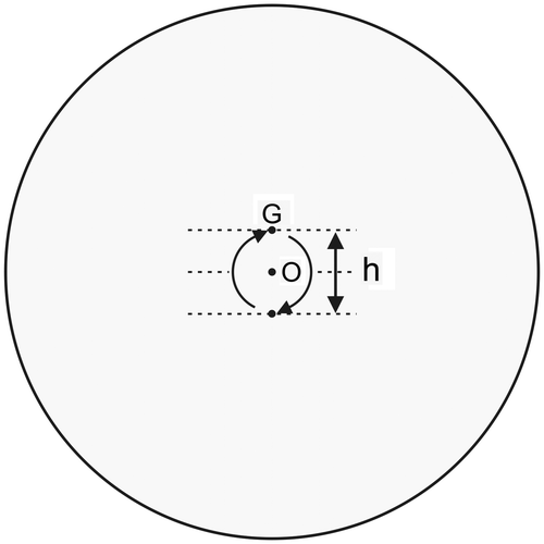
Moreover, an underlying assumption is that FFW is constant within a flywheel suspended from the basket demonstrated that the belt tension is not constant during a pedal revolution (Franklin et al., Citation2007). For example, with a 2 kg weight, flywheel speed decreased from 70 to 0 rpm in 4.65 s, with 24–25 oscillations of FT (around 5.3 Hz) whose magnitudes were equal to or lower than 0.75 N (3.75% of FT). Seck et al. (Citation1995) suggested that the belt tension varies significantly within a flywheel revolution because the flywheel is not perfectly round and centered. Another explanation is variations of the friction coefficient. The friction coefficient μ is assumed to be constant for the flywheel sliding on the belt in spite of the local effects of stain, dust, and irregularities on μ and possible differences in μ between the belt and the rope. The mean of μ increases when the part of the flywheel with the highest friction coefficient slides on the part of the belt-rope with the highest tension.
The control of FFW by the pulley-belt-weight system can be compared with a spring-mass system that oscillates in the absence of damping. The magnitude of the oscillations can be reduced by increasing the damping effect of external dissipative forces such as friction forces. Unfortunately, these forces mainly correspond to the friction force on the pulley axis in the case of MonarkTM ergometers and this friction must be as low as possible to minimize the error in FFW. In addition, at the beginning of the sprint without a rolling start, the system switch from a static friction coefficient (μs) + the basket in a low position to a dynamic friction coefficient (μk) + the basket in a high position. Therefore, the behavior of the pulley-belt-weight system at the beginning of the sprint is equivalent to the impulse response of an underdamped control system.
In theory, oscillations of Pcorr can also be the result of computing approximations and errors in flywheel rotation measurement. For example, the sensitivity of the flywheel-motion transducer was equal to 1° in the study by Seck et al. (Citation1995). Given the ratio between the sprockets (52/14), flywheel angular displacement is equal to 3.714 times the crank angular displacement and one pedal revolution corresponded to 1,337 impulses. These variations were computed as equivalent to accelerations of the flywheel (Seck et al., Citation1995). For example, at 120 rpm, the impulse frequency is 2,674 impulses s−1 and for a 20 Hz sampling rate, the number of impulses in 50 ms was equal to 133 (2674 × 0.05 s). Therefore, ±0.5 impulse corresponded to relative errors in V equal to ±0.38%. The studies comparing corrected and uncorrected power outputs generally used a commercially available software package (Cranlea Wingate testing kit version 2.21, Cranlea, UK) with a sampling rate around 20 Hz (James, Wood, Maberly, & Croix, Citation2007). The sensitivity of the flywheel-motion transducer was equal to 2° in the studies by James et al. (Citation2007) or Smith et al. (Citation2007), which corresponded to computation errors in V about ±0.75% at 120 rpm.
Differences between the right and left legs and revolution-to-revolution fluctuations in muscle activation (Vandewalle, Maton, Le Bozec, & Guerenbourg, Citation1991) are possible biological causes of oscillations in Fcorr and Pcorr. In the case of a significant difference between the maximal power of the right and left legs, optimal pedal speed must be reached when the most powerful leg is pushing on the crank. The effect of a difference between the maximal power of the right and left legs upon PPcorr should be more important at low brake torque because of the large variation of pedal speed between the beginning and end of a pedal revolution (see above). Biological causes of oscillations should interact with biomechanical factors (e.g. the degrees of freedom of cycling exercises). In theory, if the activations of all the agonistic and antagonistic muscles which exert their actions on the knee, ankle, and hip were similar in all the subjects and constant, there would be only one degree of freedom for cycling exercises. Otherwise, the same pedal rotation can be produced by different combinations of knee, ankle, and hip extensions and there would be three degrees of freedom for cycling exercises. Therefore, variations in the activations of the different leg muscles could contribute to oscillations in Pcorr.
Appendix 2
In the study by Gordon et al. (Citation2004), a linear regression between lnFT and lap angle θ was expected in agreement with the relationship between FT, μ, and θ:
ln (FT/9.98) = μθ
The correlation coefficient between FT and θ was very high (r = 9978). Consequently, the regression between the experimental values of FT and θ was assumed to be linear and the slope (0.175) was considered as an accurate estimation of μ. In spite of the very high value of the correlation coefficient, the linearity of the relationship was questionable. Indeed, the “pure” error in lnFT (the differences between each lnFT-value and the mean of the three LNFT-values corresponding to the same lap angle) was very small for several lap angles (225°, 270°, and 450°) when compared to the errors due to the prediction of lnFT from the computed linear regression. The linearity of the regression between θ and lnFT can be verified with a lack-of-fit test based on variance analysis and a F test:
F = (A/dofA)/(B/dofB)
where A was the sum of squares due to lack-of-fit of the model, B the sum of squares due to pure errors, dofA the degree of freedom of A, and dofB the degree of freedom of B. The sums of squares A and B can be computed from the values of FT presented in Table 1 of the study by Gordon et al. (Citation2004). As there were 3 measures for a given lap angle and 11 lap angles (from 45° to 495°) the total numbers of measures (N) was equal to 33 (N = 3n = 33) and dofA and dofB were equal to 9 (n − p = 11 − 2) and 22 (N − n = 33 − 11), respectively. The lack-of-fit test for a linear regression was highly significant (F22,9 = 15.19; p < 0.01). Therefore, the experimental regression could not be considered as linear. This discrepancy between the theoretical linear model and the experimental data could be explained by errors in lap angles (θ) and/or errors in FT. Moreover, the Y intercept (−0.066) of the θ-lnFT regression was significantly different from zero. Therefore, it was possible that the slope (0.175) of the linear θ-lnFT regression was an overestimation of friction coefficient μ. For example, the slope of the line passing by zero and the point corresponding to the mean of all the experimental data (θ = 4.712 rad and lnFT = 0.765) was equal to 0.162. In addition, the slope of θ-lnFT regression was probably not very different for θ ranging between 45° and 180° (friction of the only belt on the flywheel) and θ ranging between 45° and 495° (friction of the belt + rope). Consequently, the coefficient of friction of the belt (μ1) was close to the coefficient of friction of the rope (μ2).
Similarly, for actual basket weights between 1.007 and 6.051 kg, the actual values of k (mean = 5.70) during cycling exercises ranged between 4.95 (for 6.051 kg) and 9.54 (for 1.007 kg), which corresponded to β between 1.60 and 2.26 (mean = 1.74). Therefore, the estimated value μ was not constant and equal to 0.175 with the different loads but ranged from 0.154 to 0.217 (mean = 0.168) for θ = 10.4 rad.
Appendix 3
In the study by Franklin et al. (Citation2007), the belt-rope was wound around the flywheel 1.65 times (θ = 10.4 rad) and ratio rS/rT was equal to 0.45. According to Figure in this study, for FB = 2 kg (19.62 N), FT and FS were equal to 20 and 0.8 N, respectively.
As k = eβ
For FB = 8 kg, ratio FFW/FB = 0.87 according to Figure 3 in the study by Franklin et al. (Citation2007). If k and f are, respectively, equal to ratios FT/FS and FFW/FB, the relationship between k and f is:
Let h2 and h8 be the fractions of θ corresponding to the windings of the belt around the flywheel for FB equal to 2 and 8 kg, respectively.
For FB = 19.6 N
θ1 = h2θ and θ2 = (1 − h2)θ
β = h2θμ1 + (1 – h2)θμ2 = 3.219
For FB = 78.5 N
θ1 = h8θ and θ2 = (1 − h8)θ
β = h8θμ1 + (1 – h8)θμ2 = 1.543
Hence:
where D = h2 − h8
As the radius of the flywheel was equal to 0.26 m, a 1-cm descent of the basket corresponded to an h2 − h8 difference equal to 0.006. The moving down of the basket from the position corresponding to 2 kg to the position at 8 kg was probably lower than 0.15 m (D = 0.09) in the study by Franklin et al. (Citation2007). Ratio μ1/μ2 has been computed for differences between h2 and h8 equivalent to descents of the basket inferior to 0.15 m (h2 − h8 < 0.09). The values of ratio μ1/μ2 computed for 0.5 ≤ h2 ≤ 0.9 which correspond to a decrease in k from 3.219 to 1.543 are presented in Figure .
Even for a descent of the basket equal to 0.15 m, ratio μ1/μ2 was lower than 0.5. Moreover, for h2 equal to 0.8 and 0.9 (θ1 = 5.03 and 5.65 rad) μ1/μ2 was even negative (curve in red in Figure ), which was not possible.
Figure 24. Relationship between ratio μ1/μ2 and descent (D) of the basket from a basket weight equal to 2 kg to a weight equal to 8 kg.
