 ?Mathematical formulae have been encoded as MathML and are displayed in this HTML version using MathJax in order to improve their display. Uncheck the box to turn MathJax off. This feature requires Javascript. Click on a formula to zoom.
Abstract
We have performed thermo-mechanical and electrical tests on epoxy resin samples used for semiconductor packaging applications. The reported resins are commonly used in Texas Instrument Incorporated products. The study was performed to better understand the influence of the resin system on physical properties of mold compounds, which are composed of mainly epoxy resin and inorganic filler particles. The results illustrated that the estimated glass transition temperatures, , for the three unfilled systems were lower than those observed in filled systems and reported by the supplier. Additional computer simulations performed using molecular dynamics yielded higher glass transition temperatures than the experimental ones, however, one needs to be cautious due to the time scales used in the simulations. The electrical conductivity values were obtained from the time domain measurements, and they illustrated that the materials have minor differences in their temperature-dependent conductivity below 130
C, while above
formulation differences could be observed and correlated to thermo-mechanical measurements.
Public Interest Statement
Semiconductor packaging involves many different materials both to connect chips to external circuits via conductor but also to protect them from the external (harsh) environment. Non-conducting (ceramic or polymeric) materials are employed to protect the chips. These materials should have specific physical properties to allow the chip function properly. External part of the chips might contain highly filled polymeric composites called encapsulation mold compounds. Most of the research on such materials has been performed using end-products without any special attention given to the employed polymeric resins. In the current contribution we, on the other hand, study on the unfilled resin systems and report their physical properties. It is clear that the base resin systems have some influence on the overall physical properties; however, they are not the single contributor. We understand the challenges of producing unfilled resin systems and appreciate the interest of the supplier. Our interaction and communication with materials suppliers are key development paths for improving materials’ capabilities in the semiconductor industry.
1. Introduction
Mold compounds used in semiconductor packaging composed of mainly epoxy resin and filler particles (Lu & Wong, Citation2009; Wong & Wong, Citation1999). The epoxy is a two-component system formulated with a base resin and a hardener, such that ratio of resin to hardener defines the cross-linking density, as well as the physical properties—the hardener and the base resin react and crosslink to form the thermoset plastic. Different chemistries can be found in the literatures Lu and Wong (Citation2009) and Rimdusit and Ishida (Citation2000).
Physical properties of the mold compound are mainly defined by the resin/hardener system, when thermo-mechanical and electrical properties are considered. A review about the physical properties of filled mold compounds have been recently published Yao et al. (Citation2012), however, it is valuable to investigate the physical properties of the unfilled, pure resin systems to comprehend the influence of the base resin intrinsic properties on the actual semiconductor packaging mold compounds. There are practical implications to fabricate unfilled resin samples, where the starting materials are solid components, as in the semiconductor packaging, where solid resin and hardener particles are mixed in powder form, then cured via thermally activated process. Therefore, the homogeneity of the mixture becomes important for the final product. Just to note, the studied systems were amber colored transparent parts with dark spots in them indicating presence of some heterogeneity.
The materials studied in this work were supplied by Sumitomo Bakelite Co., Ltd. USA. Three different unfilled resin samples to our Dallas Packaging Materials Laboratory were delivered, notice that it has been hard to investigate unfilled mold compound systems for some time because of the difficulties in fabricating samples with conventional methods. Here, we report our initial studies on the physical properties of these different thermoset systems, and would like to draw attention to the composition–property relationship in micro-electronics packaging materials.
Table 1. Resin systems and their components
2. Materials and methods
Material designations and compositions are tabulated in Table . The materials were prepared and fabricated by the supplier. The samples were two-component epoxy systems, composed of resin and hardener. As can be seen in Table , depending on the system either one (multi aromatic resin) or two resin systems employed (Lu & Wong, Citation2009; Mogi & Yasuda, Citation1992). The similar was true for the hardeners as well. Observe that Sample B could be considered as a baseline system, however, one needs to be careful due to the lack of information on the details of molecular weights and constituting parts of the MAR systems in each resin. The samples were supplied as coupons for electrical measurements and a block for thermo-mechanical characterization. The materials were supplied without post-mold treatment, and were post-mold cured for 4hr at 175C in our laboratory. Following measurement methods were used for characterization;
Differential scanning calorimetry (DSC)
Thermo-mechanical analysis (TMA)
Thermo-gravimetric analysis (TGA), and
Time-domain electrical conductivity analysis (TDECA).
Great care must be given to the measurements since the cure profiles influences the physical properties of the mold compounds (Gonon, Sylvestre, Teysseyre, & Prior, Citation2001; Mogi & Yasuda, Citation1992). During the thermo-mechanical analysis the samples experienced temperatures up to 300C. The procedure for TMA used a temperature ramp from 0
C to 260
C (heating) and down to 0
C (cooling), we use the measurement results from the cooling rate due their accuracy around the glass transition. The TGA measurements were performed with 10
C/min ramp up to 600
C to see the whole weight loss behavior in samples. In the TDECA the maximum temperature was 150
C, which is lower than the cure temperature; no influence of any further cure should have influence on the electrical conductivity measurement. The conductivity measurement was described elsewhere in detail Tuncer (Citation2016) and Tuncer (Citation2014). Depending on the method either one or two samples were measured, therefore, no standard deviation on the sample-to-sample variation could be derived. In addition, notice that it is our experience that the sample-to-sample variations in physical properties of mold compounds from the same batch do not show any significant differences in the measured properties.
3. Results
3.1. Thermo-mechanical characterization
3.1.1. Differential scanning calorimetry
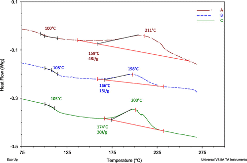
The DSC results are shown in Figure for 5C/min heating rate. The analysis of the data are also indicated in Figure , where the energy for the reactions as well as the anticipated glass-transition temperatures are labeled. The energy was estimated using the curves over the straight lines in the figure for each reaction. The reaction start temperature for each material is also indicated above the exothermic reaction energy. The baseline material (B) is the least reactive of all with 15 J/g, while Sample C releases the most energy during the cure reaction and its reaction started at a lower temperature and had a wider peak than the other two resin systems. The multi-functional part influences the cure kinetics and introduces a low-temperature onset in the reaction. The differences between the formulations/compositions indicate that MF resin modifies the base resin system and releases more than double the energy during the curing. While, the DCPD resin with toughening agent in the hardener has little effect on the temperature of the reaction. The glass-transition temperatures of the materials are listed in Table , which do not indicate significant differences. It is our experience that the glass transition temperatures
of mold compounds would be different depending on the batch tested;
or any property of the materials should be considered as a distribution, not an exact value.
3.1.2. Thermo-mechanical analysis
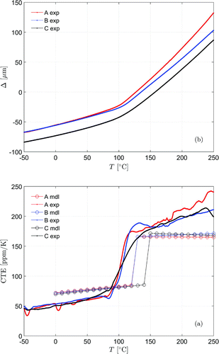
The TMA was used to determine the glass-transition temperature and the coefficient of thermal expansions (CTEs) below and above glass transition. The measurement results are shown in Figure (a) together with the modeling estimation of the CTEs from molecular dynamics simulations performed using molecular dynamics (Rigby, Citation2015) in Figure (b). There are discrepancies between simulations and measurements which are correlated to the time constants used in the simulations, which resulted in underestimates of the measurement values; the reason for this is the heating rate in the simulations was significantly high 1
C/ns(=
C/min). While the numerical simulations have been useful to illustrate compositional differences in the studied resin systems, actual measurements might be more valuable for design purposes. The parameters used in the numerical approach (the MedeA®-LAMMPS graphical interface) (Rigby, Citation2015). The approach had the following procedure: (i) Preliminary molecular mechanics minimization to ensure a ground state without large internal forces: (ii) Short time (50 ps) constant volumemolecular dynamics simulation with a default fast (1 fs) integration time step to ensure a spatially uniform packing of molecules: (iii) Constant pressure molecular dynamics simulation of with the same duration (50 ps) to achieve a density around 1.05 gcm
: (iv) Scaling to the target density followed by a short time (50 ps) constant volumemolecular dynamics at a temperature of 523 K: (v) Limit sharp energy/force cutoff at a separation of 9.5 A for less expensive (fast) computation. Later MedeA®Thermoset Builder Rigby (Citation2015) was introduced to solve for the crosslinks into the model at the location of the components (resin and hydroxyl groups).
The investigated materials had similar CTEs below around 50 ppm. Numerical values over estimated the values. Sample C has indicated a broader
region compared to other two resins, which can be related to the broadening of the reaction peak in DSC; more sides to react yielding more locations of vibrational relaxations. The physical parameters are summarized in Table , where small variations between the materials exist over
.
3.1.3. Thermo-gravimetric analysis
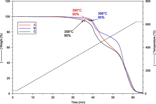
Information on the weight loss of samples are important for applications since for high-temperature operation the materials would age and physical properties degrade fast if they indicate any weight loss. In addition it gives us information on the bond strength and how the materials decompose. Finally, if any, filler content can be also obtained directly from the TGA measurements. The results showed that the materials have similar compositions because of the humps and location of them, see Figure . The estimated 5 loss temperatures yield that Sample C has the lowest temperature of decomposition about 358
C. The other two were closer to 400
C; indicating that the MF portion of the resin has a low degradation temperature point. A similar observation can be mentioned for the DCPD resin in Sample A which indicates a slightly lower degradation point than Sample B.
Observe that these values are short time weight loss results, long time weight loss at isothermal conditions would be a more illustrative method to better characterize the materials aging. As mentioned previously there are no fillers in the studied systems, confirmed with 600C remaining weight of materials left in the TGA was zero grams.
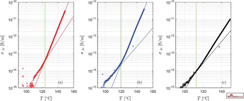
Figure 4. Comparison of electrical conductivity of the studied mold compound resins (a) Sample A, (b) Sample B, and (c) Sample C. The solid lines represent the curve fits using the exponential expression in Equation (1). The vertical lines illustrate the location of the glass transition estimated from the intersection of Equation (1) with parameters listed in Table .

3.2. Electrical characterization
Electrical properties of the materials, their conductivity , show strong contribution of ionic charge transport due to the behavior of the conductivity
versus temperature curves; they are log-linear type and could be expressed with an exponential curve,
(1)
(1)
Here, the direct-current conductivity is expressed with a straight forward exponential expression with two unknowns, pre-exponent
and critical temperature
in Kelvin units.
The change in the conductivity behavior was attributed to the glass transition temperature , which is estimated from Equation (1) below and above specific temperature ranges. The obtained results are also illustrated in Figure with solid lines. The number of data points below
is scarce due to the limitation in the measurement current which allows the employed system to measure conductivities higher than 1 fS/m. Other curve fitting methods could also be applied to describe the data as listed in elsewhere Tuncer, Wegener and Gerhard-Multhaupt (Citation2005) and Tuncer, Wegener, Frübing, and Gerhard-Multhaupt (Citation2005).
Compositional differences in Samples B and C yield clear separation between conductivities over 130C with Sample C having the lowest conductivity at high temperatures. Sample A has nearly the same behavior as Sample B, but shifted down over the temperature range, see Figure . These observations show that the content of the additional resin components, DCPD and MF in Samples A and C, respectively, have been different in the reformulations of the resin systems; The conductivity data for Samples A and B have similar behavior over
, and their
estimates are within 5
C with the resin modification.
Table 2. Summary of the physical parameters of the studied resin systems
Table 3. Electrical characterization of the samples using two Arrhenius curves to represent the data below and above the glass transition temperature. The values are estimated using Equation (1) above and below glass transition
4. Discussion and conclusions
There are differences between the physical properties of the studied three resin systems. The base resin Sample B had been modified to obtain other two resins. The reaction kinetics and decomposition temperatures were altered with the composition differences. The summary of the results are presented in Table . It looks like the glass transition temperatures estimated with three different methods yield varied results with the same trend yielding Sample C has the lowest of all. We were not provided with the details of the formulations of each system, however, our analysis indicate that Sample A and Sample B are close in formulation when their physical properties are compared. The degradation temperatures were close for these two resin as well their electrical behavior. This could, as mentioned before, be attributed to a slight modification made in the base resin, Sample B; the amount of DCPD in Sample A only influenced the CTE over
. The reason for using DCPD could be to improve the mechanical properties by increasing the CTE of the material; it becomes a lower modulus mold compound with better adhesion performance in semiconductor packaging. Sample C has a broader reaction window with low degradation temperature from TGA results. It is interesting to observe that the
values of the materials were low about 106
4
C from thermo-mechanical measurements, while the electrical measurements yield higher
values than DSC and TMA. The numerical simulations yield completely opposite trend in the experimental findings, where Sample C has the highest
. The results obtained for Sample C have indicated the large discrepancies in physical properties compared to the other two systems that were contributed to the modification made by MF resin and its content. The electrical and degradation performance of the resin were the indicators.
One surprising result is that our experience with the actual mold compounds formulated with silica fillers using the represented resin systems here yield values around 105
C-125
C for Samples A and Sample B, and 150
C-165
C for Sample C, which is an unexpected result because the unfilled resins do not indicate such
values, especially in the case of Sample C. One should not disregard the importance of other additives, e.g. surface functionalization agents for filler particles, stabilizers, release agents, wax, etc., on the physical properties of the mold compounds. It appears as if in Sample C the influence of the other additives have influenced the electrical properties as well as the mechanical properties.
To compare our results with those in literature was not straight forward. There is lack of volumeresistivity or electrical conductivity data available. Ion transport in two different resin systems, epoxy cresol novolac and biphenyl resin, previously reported in the literature Lantz and Pecht (Citation2003), however, no information on the temperature-dependent conductivity in those materials were shared with respect to the conductivity of the resins. Another epoxy system based on diglycidyl ether of bispenol-A studied by Tian and Ohki, and the data have been published several times Tian and Ohki (Citation2014), Tian and Ohki (Citation2013), Tian and Ohki (Citation2013), showed conductivity of 36 pS/m and 304pS/m at 125C and 150
C , respectively. Although the material is not extensively used in the semiconductor packaging, electrical conductivities were much higher than the values reported here for the current materials. The presented values in those papers were estimated from the alternating current measurements including the displacement currents, which could be due to the measurement method. A recently published review Yao et al. (Citation2012) lists physical properties of many resin systems, however, they did not include the volumeresistivity or electrical conductivity of the materials as important properties for the power electronic packages. Notice that one of the aims of using mold compounds in semiconductor packaging is electrical insulation purpose, and there are requirements (Dakin, Citation1978).
Although it might be of interest to study the unfilled resin systems, it is our conclusion that the composite nature of the mold compound defines the physical properties of semiconductor packaging mold compounds. The additives like fillers and functionalization agents used to improve compatibility between filler and the resin influence the physical properties significantly. Further studies are needed to investigate the influence of constituents in mold compound formulations on physical properties. Suppliers might have the know-how from Edisonian (trial-and-error) approach using one property at a time, however, more fundamental work is needed for functional mold compounds employing material-by-design technique.
It was our intention here to draw attention to the lack of information on the electrical properties of mold compounds.
Acknowledgements
We thank Mr Hironari Mori from Sumitomo Bakelite Co., Ltd. for supplying the samples. We appreciated their kindly support here. The numerical simulation were performed by Materials by Design Inc. San Diego CA through a collaboration between Texas Instruments Incorporated, Sumitomo Bakelite Co. Ltd and Materials by Design Incorporated (Rigby, Citation2015).
Additional information
Funding
Notes on contributors
Enis Tuncer
Enis Tuncer and Alex Hernandez-Luna are Packaging Engineers at Texas Instruments Incorporated in Dallas Texas. They received their PhD in High Voltage Engineering and Materials Science and Engineering, respectively, from Chalmers University of Technology in Gothenburg Sweden and University of North Texas in Denton Texas USA. Their main research interests have recently been in polymeric materials employed in semiconductor industry, especially the highly filled mold compounds for semiconductor device encapsulation. They have been focusing on the glass transition temperature and physical properties of epoxy resin systems to improve semiconductor device reliability. Enis Tuncer has been performing research activities on soft dielectrics for electromechanical applications, polymer physics, and dielectric mixtures for high voltage applications since 1997. Enis Tuncer is one of the associated editors of the IEEE Transactions on Dielectrics and Electrical Insulation and a Fellow of the Institute of Physics.
Alex Hernandez-Luna
Alex Hernandez-Luna has worked withsemiconductor packaging technologies, with particular interest in performance and characterization of materials used in assembly2000.
References
- Dakin, T. W. (1978, August). High voltage insulation applications. IEEE Transactions on Electrical Insulation , EI-13(4), 318–326.
- Gonon, P. , Sylvestre, A. , Teysseyre, J. , & Prior, C. (2001). Dielectric properties of epoxy/silica composites used for microlectronic packaging, and their dependence on post-curing. Journal of Materials Science: Materials in Electronics , 12 (2), 81–86.
- Lantz, L. , & Pecht, M. (2003). Ion transport in encapsulants used in microcircuit packaging. IEEE Transactions on Components and Packaging Technologies , 26 (1), 199–205.
- Lu, D. , & Wong, C. (2009). Materials for advanced packaging (Vol. 181). New York: NY: Springer.
- Mogi, N. , & Yasuda, H. (1992). Development of high-reliability epoxy molding compounds for surface-mount devices. In Electronic Components and Technology Conference, 1992. Proceedings, 42nd (pp. 1023–1029).
- Rigby, D. (2015). Atomistic simulations of high voltage packaging materials. Materials Design Incorporated . Internal report prepared for Texas Instruments and Sumitomo Bakelite by Materials Desing Inc.
- Rimdusit, S. , & Ishida, H. (2000). Development of new class of electronic packaging materials based on ternary systems of benzoxazine, epoxy, and phenolic resins. Polymer , 41 (22), 7941–7949.
- Tian, F. , & Ohki, Y. (2013). Charge transport and electrode polarization in epoxy resin at high temperatures. Journal of Physics D: Applied Physics. , 47 (4), 045311.
- Tian, F. , & Ohki, Y. (2014). Electric modulus powerful tool for analyzing dielectric behavior. IEEE Transactions on Dielectrics and Electrical Insulation , 21 (3), 929–931.
- Tuncer, E. (2014, October). Discussion on impedance measurements and bulk ohmic conductivity in lossy dielectrics. 2014 IEEE Conference on Electrical Insulation and Dielectric Phenomena (CEIDP) (pp. 844–847).
- Tuncer, E. (2016, October). Comparison of conductivities obtained from dielectric spectroscopy and time domain measurements. 2016 IEEE Conference on Electrical Insulation and Dielectric Phenomena (CEIDP) (pp. 768–770).
- Tuncer, E. , Wegener, M. , Frübing, P. , & Gerhard-Multhaupt, R. (2005). Origin of temperature dependent conductivity in α-polyvinylidene fluoride. Journal of Chemical Physics , 122 , 084901.
- Tuncer, E. , Wegener, M. , & Gerhard-Multhaupt, R. (2005). Distribution of relaxation times in α-phase polyvinylidene fluoride. Journal of Non-Crystalline Solids , 351 (33–36), 2917–2921.
- Wong, C. , & Wong, M. M. (1999). Recent advances in plastic packaging of flip-chip and multichip modules (mcm) of microelectronics. IEEE Transactions on Components and Packaging Technologies , 22 (1), 21–25.
- Yao, Y. , Chen, Z. , Lu, G. Q. , Boroyevich, D. , & Ngo, K. D. (2012). Characterization of encapsulants for high-voltage high-temperature power electronic packaging. IEEE Transactions on Components, Packaging and Manufacturing Technology , 2 (4), 539–547.


