
 ?Mathematical formulae have been encoded as MathML and are displayed in this HTML version using MathJax in order to improve their display. Uncheck the box to turn MathJax off. This feature requires Javascript. Click on a formula to zoom.
Abstract
The weldability of carbon steel is determined by carbon equivalent (CE) for predicting/estimating preheat temperatures necessary for weld integrity of the weldment. The microstructure of the welded carbon steel at the heat affected zone (HAZ) plays an essential role in the mechanical properties of the weldment, thus, painstakingly selecting welding process and parameters to slowdown the cooling rate are ensued by sound weld quality and crack free weld (enhanced service performance). This research work reviews the effects of various welding processes and parameters on microstructure and mechanical properties of carbon steels in arc-based welding.
PUBLIC INTEREST STATEMENT
Carbon steels are widely used engineering materials because of their outstanding mechanical properties and cost-effectiveness when juxtaposed with other materials. However, the ease of welding these materials, majorly high carbon steel has been a challenge due to the metallurgical transformation at the heat affected zone (HAZ) and the fusion zone (FZ) triggered by the welding heat. The weldability of these materials depends on its carbon content which is evaluated by the carbon equivalent (CE) value. The higher the CEV, the lower the weldability and vice versa. The microstructural transformation at the HAZ in the course of welding is a key factor that determines the weld integrity which depends on the cooling rate. The cooling rate is affected by the selected welding parameters and processes and can be handled in such a way to prevent rapid cooling at the HAZ and FZ for better service performance.
1. Introduction
Carbon steel properties depend mainly on its carbon content which is widely used in engineering practices. It is categorized into low carbon (mild) steel widely used for heavy structural steelwork, medium carbon steel used for shaft, gearing, pressured structures and railway applications and high carbon steel used for production of springs, gear wheels, vices, cutting tools and brackets in which welding plays an essential role in their fabrication processes (Adedayo, Odebiyi, & Oseni, Citation2013; Mousavi & Kelishami, Citation2008; Poorhaydari, Patchett, & Ivey, Citation2005; Prasanna, Rao, & Rao, Citation2010).
Welding being the most common permanent metal joining fabrication (machine parts and structures) process is the joining of two similar (steels-steel/Aluminium-Aluminium) or dissimilar (Aluminium stainless steel) metals by fusion with or without the application of pressure and with (homogeneous/heterogeneous) or without the use of filler metal (autogenous) (Etin-Osa & Achebo, Citation2017; Pamnani, Vasudevan, Jayakumar, Vasantharaja, & Ganesh, Citation2016; Khurmi & Gupta, Citation1997; Soy, Lyibilgin, Findik, Oz, & Kiyan, Citation2011; Boumerzong, Derfouf, & Baudin, Citation2010; Kumarkhamari, Sahu, & Biswal, Citation2018;). To achieve a sound weld-integrity with enhanced service performance of welded carbon steel, selection of welding processes and parameters are important (Adedayo et al., Citation2013; Balasubramanian, Varahamoorthy, Ramachandran, & Muralidhavan, Citation2009; Cvetkovski, Slavkov, & Magdes, Citation2003; Kumar, Arya, & Saxena, Citation2014; Samir, Citation2015; Singh, Citation2012).
However, weldability of carbon steel is the property that shows the ease with which they can be welded (Adedayo et al., Citation2013). It is a function of carbon equivalent estimated from the chemical composition of the steel (Adedayo et al., Citation2013; Khaled, Citation2014; https://www.productionmachining.com/articles/material-influences-on-the-weldability-of-carbon-steel).
Increase in carbon content decreases the weldability of carbon steel. Thus, high carbon steel has low weldability when juxtaposed with medium carbon and low carbon (mild) steels due to the vulnerability of microstructure of high carbon steel (martensitic microstructure upon cooling from welding heat) to cold cracking (Hinton & Wiswesser, Citation2008; Khaled, Citation2014). The weldability of carbon steel can be checked-mate by the cleanliness of weldment and the heat affected zone (HAZ) characteristic (https://nptel.ac.in/courses/112107090/module1/lecture2/lecture2.pdf; https://nptel.ac.in/courses/112107090/module8/lecture5/lecture5.pdf). Cleanliness of weld metal has to do with the presence of inclusion in the form of slag or gases whereas HAZ properties are primarily controlled by the depth of hardness of the carbon steel (https://nptel.ac.in/courses/112107090/module1/lecture2/lecture2.pdf; https://nptel.ac.in/courses/112107090/module8/lecture5/lecture5.pdf). Proper shielding of the arc zone and degassing of molten weld metal can be used to control the cleanliness of the weldment. The characteristics of the heat affected zone are one of the significant factors to be considered when examining the soundness of the weld joint integrity (Adedayo et al., Citation2013; Graville, Citation1973; Hinton & Wiswesser, Citation2008; Khaled, Citation2014; Rizvi, Tewari, & Ali, Citation2013; Sloderbash & Pajak, Citation2015; https://nptel.ac.in/courses/112107090/module1/lecture2/lecture2.pdf; https://nptel.ac.in/courses/112107090/module8/lecture5/lecture5.pdf; https://www.steeltank.com/Portals/0/Articles/Effect%20of%20Chemical%20Elements%20in%20Steel.pdf?ver=2009-05-31-010753-797). The HAZ is considered as a misfit as a result of the microstructural changes owing to the welding heat which triggers a very rapid heating and cooling rates (Graville, Citation1973). The carbon equivalent of carbon steel is considered as the main factor in estimating preheat, and the higher the carbon content of the steel, the greater the tendency to form a hard and brittle HAZ. Thus, this necessitates the use of preheating and low hydrogen electrodes (https://www.productionmachining.com/articles/material-influences-on-the-weldability-of-carbon-steel). Carbon and manganese, however, are not the only element that influences the depth of hardness and reduction in ductility of carbon steel that comes with the rapid cooling (Adedayo et al., Citation2013; Khaled, Citation2014; Rizvi et al., Citation2013; https://www.steeltank.com/Portals/0/Articles/Effect%20of%20Chemical%20Elements%20in%20Steel.pdf?ver=2009-05-31-010753-797). A critical time ’’ for a martensite-free HAZ in Carbon steel can be established from a developed carbon equivalent defined as highlighted in Equationequations 1
(1)
(1) –Equation12
(12)
(12) :
European standard EN 1011–2 Method A is given as; (Hinton & Wiswesser, Citation2008; Khaled, Citation2014)
European standard EN 1011–2 Method B is given as; (Hinton & Wiswesser, Citation2008; Khaled, Citation2014)
AWS D1.1–2000 a CE called Critical Metal Parameter is given as; (Khaled, Citation2014)
The Hardness Control Method is given as; (Khaled, Citation2014)
The Skoda(Czechoslovakia)Method is given as; (Hinton & Wiswesser, Citation2008; Khaled, Citation2014)
The Winn Method is given as (Hinton & Wiswesser, Citation2008; Khaled, Citation2014)
This equation, EquationEquation 12
(12)
(12) is applicable to both the traditional steels covered by
, and the mild steels upon which the critical metal parameters were generated. This resulted to the hyperbolic “tangent
term” in the accommodation factor
. The
and
approach
and 1, respectively, as the peak carbon levels. On the contrary,
approaches
at lower carbon levels (Khaled, Citation2014; Hinton & Wiswesser, Citation2008; Murugan, Kumar, Gill, Raj, & Bose, Citation1999; https://www.steeltank.com/Portals/0/Articles/Effect%20of%20Chemical%20Elements%20in%20Steel.pdf?ver=2009-05-31-010753-797; https://nptel.ac.in/courses/112107090/module1/lecture2/lecture2.pdf; https://nptel.ac.in/courses/112107090/module8/lecture5/lecture5.pdf). This paper therefore serves to review the weldability of carbon steels using the available literature in order to determine the appropriate welding process and parameters combination that influence the mechanical and microstructure properties of the heat affected zone, fusion zone and the parent metal in an arc-based welding process for better service life.
2. Welding parameters
Welding parameters such as current, voltage, speed, thermal efficiency and heat input of welding affect the weld quality of carbon steel weldment.
2.1. Heat input
Welding Heat input is defined by EquationEquation 13(a(13a)
(13a) –c)
For instantaneous energy measurements in joule
For instantaneous power measurements in J/s or W
Where V and I are the arc voltage (volts) and current (amp.), respectively,
S is the welding speed mm/min, and K is the thermal efficiency for the welding process (Kumar et al., Citation2014; Liskevych & Scotti, Citation2015)
From Figure , the heat affected zone of the weldment improved as the heat input of the welding process increases.
Figure 1. variation of HAZ width with heat input (Poorhaydari et al., Citation2005)
Table and Figure show the effect of heat input on the cooling rate of the weldment, as the heat input increases (1.46KJ/mm to 7.28KJ/mm) the cooling rate of the weldment decreases from 12.5/sec to 2.5
/sec.
Table 1. Calculated heat input and cooling rate (Kumar et al., Citation2014)
Figure 2. Effect of heat input on cooling rate (Samir, Citation2015)
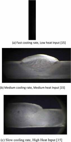
As the heat input increases, the microstructure of the heat affected zone (HAZ) is more refined from cold cracking (martensite formation) by slowing down the cooling rate. The grains at the fusion zone are larger for the slow cooling rate when juxtaposed with the other fusion zone (FZ) of fast and medium cooling rates weldments, respectively, as shown in Figure –c).
Figure 3. (a) Fast cooling rate, low heat input (Kumar et al., Citation2014), (b) Medium cooling rate, medium heat input (Kumar et al., Citation2014), (c) Slow cooling rate, high heat input (Kumar et al., Citation2014). (a–c): Macrographs of weldment at a different cooling rate and heat input at 7x magnification. (Kumar et al., Citation2014)
2.2. Welding current
Table shows the effect of welding current on the heat input in the course of the welding process. It can be noted that the welding current increases from 80Amp to 100amp as the welding heat input increases from 942J/mm to 1178J/mm. The weldment hardness and heat affected zone increased up to 90amp then decreased. (Samir, Citation2015)
Table 2. Effect of heat input controlled by a change in welding current (Samir, Citation2015)
Figure ) shows an increase in hardness at the heat affected zone of the weldment compare to weld joint and base metal in all the specimens. The cooling rate decreases in parabolic pattern with an increase in current as shown in Figure ) with the solidification time increasing in a straight line as shown in Figure ).
Figure 4. (a) Change in hardness zones in the weld joint. (Samir, Citation2015). (b) Change in cooling rate. (Samir, Citation2015). (c) Change in solidification time. (Samir, Citation2015)
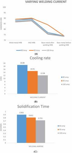
As a result of this increase in welding current up to 90 amp, the more bainitic lathe is formed in lieu of pearlite which results in increased hardness. However, with further increase in current, welding heat input increases and leads to an extra normalizing effect on the weld with a resulting decrease in hardness (Samir, Citation2015)
2.3. Welding voltage
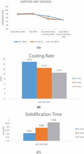
As the welding arc voltage increases from 21 volts to 25 volts, the width of the weld joint and the heat input increase from 1060 J/mm to 1262 J/mm with a decrease in penetration as shown in Table . The arc voltage has more influences on the welding heat input than the welding current. (Samir, Citation2015)
Table 3. Effect of heat input controlled by a change in welding voltage (Samir, Citation2015)
There exist a maximum difference in the change in hardness of the workpiece at 21 volts, with greater hardness value at the heat affected zone in all the workpieces as depicted in Figure (a). The hardness of the weld joint decreases in all the three regions (HAZ, weld metal, and base metal) as the arc voltage increases and the cooling rate, decreased with an increase in arc voltage as depicted in Figure (b). the solidification time of the weld increases as the welding arc voltage increases in a linear pattern as shown in Figure ) (Samir, Citation2015)
Figure 5. (a) Change in hardness zone wise in the weld joint (Samir, Citation2015). (b) Change in cooling rate (Samir, Citation2015). (c) Change in solidification time (Samir, Citation2015)
2.4. Welding speed
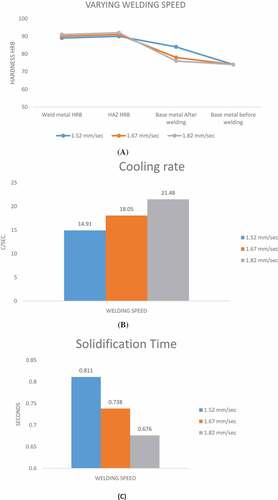
Welding heat input decreases as the welding speed increases as a result of the reduction in time for arcing during welding. The hardness values of both the heat affected zone and the weldment were increased with an increase in welding speed as shown in Figure ) and Table respectively (Samir, Citation2015). Cooling rate increases with increase in welding speed and solidification time decreased abruptly, thus giving room for martensitic transformation at the heat affected zone and weldment hardness increases with increase in welding speed as shown in Figure ,c) respectively. Additionally, penetration of the weld increases up to optimum welding speed and then decreases while the width of the weld joint decreases with an increase in welding speed (Samir, Citation2015)
Table 4. Effect of heat input controlled by a change in welding speed (Samir, Citation2015)
Figure 6. (a) Change in hardness zone wise in the weld joint. (Samir, Citation2015). (b) Change in cooling rate. (Samir, Citation2015). (c) Change in solidification time. (Samir, Citation2015)
2.5. Thermal efficiency
Welding processes performance is measured by thermal efficiency, high weld deposit quality, penetration and productivity of the processes. The thermal efficiency also called arc efficiency, process efficiency and heat transfer efficiency can be calculated as given in EquationEquation 14(14)
(14) ;
Where is the calorimetric energy input to the plate,
is the nominal energy input from the power supply (arc energy)
The thermal efficiency for consumable electrode processes is generally higher than the no-consumable processes. (Dupunt & Marder, Citation1995; Pépe, Egerland, Colegrove, & Yapp, Citation2011; Stenbacka, Choquet, & Hurtig, Citation2012)
Figure shows the schematic representation of the qualitative energy balance of the welding process that describes the melting efficiency and the process arc. The welding arc provides the bulk of the total energy in the welding process, and a small portion is provided by the welding electrode. The summation of these generated energies is transferred to the weld metal while a portion is lost to the welding surrounding (Dupunt & Marder, Citation1995). Mathematically, this energy balance is given as;
Since the left hand is the total energy transferred to the weld metal, the arc efficiency ( and melting efficiency (
can be expressed as in EquationEquations 16
(16)
(16) –Equation17
(17)
(17) ;
The fusion zone (FZ) is melted by a portion of the total energy transferred to the weldment while the remaining energy lost is responsible for metallurgical transformation of part of the weldment next to the fusion zone (FZ) (formation of the heat affected zone) and heating up of the remaining parts of the weldment above the room temperature (Dupunt & Marder, Citation1995; Pépe et al., Citation2011; Stenbacka et al., Citation2012).
Figure 7. Schematic diagram showing energy distribution in the welding process (Dupunt & Marder, Citation1995)
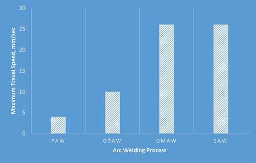
Figures and show GMAW and SAW with good arc efficiency and maximum travel speed follow by GTAW and PAW of the considered processes.
Figure 8. Comparison of arc efficiency (Dupunt & Marder, Citation1995)
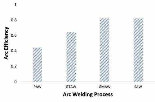
Figure 9. Maximum achievable speeds among the evaluated welding processes (Dupunt & Marder, Citation1995)
2.6. Parallel heating
Parallel heating is the operation of heating weldment at the outer boundary to some pre-determined temperature concurrently with the welding process as depicted in Figure , whereas preheating involves heating workpiece to some pre-determined temperature before commencing the real welding process. The microstructure of high carbon steel is vulnerable to cold cracking (martensitic microstructure) as a result of rapid cooling of the weldment HAZ can be altered by parallel heating which is more pronounced as the boundary heater temperatures increases. (Adedayo et al., Citation2013; Graville, Citation1973; Khaled, Citation2014).
Figure 10. Butt welded plate configuration with boundary heaters (Adedayo et al., Citation2013)
The boundary heating with high temperatures gave minimum cooling rates as shown in Table . Thus, the application of transient heat simultaneously with the welding process slows down the cooling rates, and thus, the applied heat refines the microstructures of the weldment by preventing the formation martensite (cold cracking) (Adedayo et al., Citation2013; Asibeluo & Emifonye, Citation2015).
Table 5. Cooling rates at different parallel boundary heating temperatures (BHT) (Adedayo et al., Citation2013)
2.7. Weldment thickness
The thickness of the weldment to be joined modifies the cooling rate which as a result induces the hardening and cracking tendency (Kumarkhamari et al., Citation2018; Liskevych & Scotti, Citation2015). Considering the thickness of weld metal, the carbon equivalent value is modified to achieve compensated carbon equivalent related as per EquationEquation 18(18)
(18) .
Where’ t’ is the thickness of the plate in mm.
For large weld metals, vast amounts of austenite may be available after welding if preheat temperature and interpass temperature (
) are notably higher than
(90% martensite transformation temperature) for the work piece. As cooling progresses, this austenite can transform to martensite thereby increasing the risk of cold cracking and for large base metal
and
should be below
(90% martensite transformation temperature). Thicker sections generally require higher
because of the greater heat-sinking capacity of thicker sections; heat sinking increases cooling rates producing smaller
values (Hinton & Wiswesser, Citation2008; Khaled, Citation2014).
The cooling rate is related to the thickness as per EquationEquation 19
(19)
(19) (Samir, Citation2015)
Where is the weldment thickness,
is the density of the weldment in
is the specific heat of solid metal in
is the temperature near the pearlite nose on TTT diagram
is the initial temperature of the plate to be welded in
is the heat input in
Where is the thermal conductivity in
is the initial temperature of the plate to be welded in
the temperature near the pearlite nose on TTT diagram
Where is volumetric specific heat in
The cooling rate slows down as the thickness requires more heat input as depicted in Figure —Figure
Figure 11. Heat cyclic on HAZ of plates with different thicknesses (Dong et al., Citation2017)
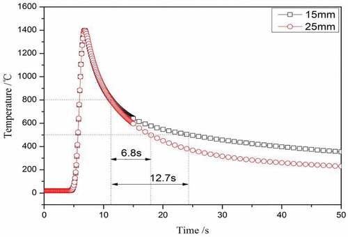
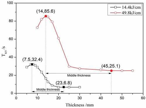
Figure 12. Effect of cooling rate t8/5 for plates with different thicknesses. (Dong et al., Citation2017)
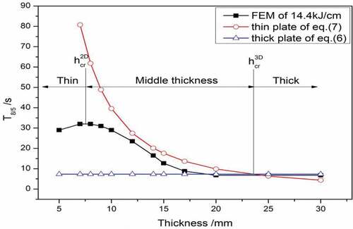
Figure 13. T8/5 with a different thickness under heat input of 14.4kJ/cm and 49.8kJ/cm (Dong et al., Citation2017)
3. Arc-based welding processes
Sir Humphrey Davy in 1800 was credited for the manufacturing of an arc between two carbon electrodes using the battery as a source of power supply in the 19th century (https://weldguru.com/OLDSITE/welding-history.html; https://www.interfacewelding.com; https://www.totalmateria.com/page.aspx?ID=CheckArticle&site=kts&NM=186). The popular arc-based welding processes are Shielded Metal Arc Welding (SMAW), Gas Metal Arc Welding (GMAW/MIG), Flux Cored Arc Welding (FCAW), Submerged Arc Welding (SAW), Gas Tungsten Arc Welding (GTAW/TIG) and a variant of GTAW process called Activated Flux Gas Tungsten Arc Welding (A-GTAW) (Balasubramanian et al., Citation2009; Cao, Jahazi, Immarigeon, & Wallace, Citation2006; Khaled, Citation2014; Khurmi & Gupta, Citation1997; Pamnani et al., Citation2016; Tsuei, Citation2000; https://nptel.ac.in/courses/112107090/module1/lecture2/lecture2.pdf).
3.1. Gas metal arc welding (GMAW)
GMAW was developed in the 1930s by H.M. Hobart (https://weldguru.com/OLDSITE/welding-history.html; https://www.totalmateria.com/page.aspx?ID=CheckArticle&site=kts&NM=186). This is also known as metal inert gas (MIG) welding process and the most common industrial welding process which requires a constant voltage and direct current power source. The arc is struck between the consumable electrode and the base metal. The four basic methods of metal transfers are spay, globular, pulsed-spray and short-circulating in which the shielding gas usually Helium, Argon or a combination of the two is externally supplied. The consumable electrode (filler wire) is fed continuously into the fusion zone automatically. MIG can be semiautomatic or automatic. In the latter, the torch or the base metal is moved relative to other mechanically while in semiautomatic MIG, the torch is manipulated manually.
3.2. Shielded metal arc welding (SMAW)
In 1950s SMAW was developed (https://weldguru.com/OLDSITE/welding-history.html; https://www.interfacewelding.com; https://www.totalmateria.com/page.aspx?ID=CheckArticle&site=kts&NM=186). This welding process is frequently utilized for welding ferrous metals in the steel structures construction and industrial fabrications. It is popularly called stick/covered electrode welding which follows a manual process in which the covered electrode uses an electric current to generate an electric arc between the base metal and the consumable electrode/stick. The molten weldment is shielded by fluxing elements provided by gas produced by the flux coating decomposition.
3.3. Submerged arc welding (SAW)
SAW was invented in Pennsylvania in the course of the defense buildup at Mckeesport in the late 1930s and early 1940s by the National Tube Company for a new pipe mill (https://weldguru.com/OLDSITE/welding-history.html; https://www.interfacewelding.com; https://www.totalmateria.com/page.aspx?ID=CheckArticle&site=kts&NM=186). The arc is between the base metal and cored consumable electrode in which the arc is being shielded by a layer of fusible granular flux (blankets and protects the fusion zone and nearby area from contamination upon melting). The weldment modification is done by the alloying ingredients present in the flux, and more than one cored electrode can be concurrently fed into the weld pool to increase rates of deposition.
3.4. Gas tungsten arc welding (GTAW)
This is also known as tungsten inert Gas (TIG) welding in which the arc is between the tungsten electrode (non-consumable) and base metal.GTAW was developed in 1890 by C.L. Coffin and later refined by Hobart in the late 1920s (https://weldguru.com/OLDSITE/welding-history.html; https://www.totalmateria.com/page.aspx?ID=CheckArticle&site=kts&NM=186). It is used to weld thick sections of high alloy steel or nonferrous metals. This process employs more time and complex than other processes. However, a variant of TIG called activated flux gas tungsten arc welding (A-GTAW) has been reported to surmount the major drawbacks of low productivity and shallow penetration in the TIG welding process. GTAW is similar to Plasma Arc Welding (PAW) developed by Robert M. Gage in 1957. More welding heat is produced in PAW than GTAW by the ionized gas. (https://weldguru.com/OLDSITE/welding-history.html; https://www.totalmateria.com/page.aspx?ID=CheckArticle&site=kts&NM=186)
3.5. Flux cored arc welding (FCAW)
FCAW was developed in 1954 by Bernard and later patented and refined by National Cylinder Gas Co. in 1957 (https://weldguru.com/OLDSITE/welding-history.html; https://www.totalmateria.com/page.aspx?ID=CheckArticle&site=kts&NM=186). This is a portable and high welding speed process developed as an alternative to shield welding. The arc is struck between the consumable cored electrode containing internally packed flux and the base metal. This welding process can be automatic or semiautomatic. The shielding gas is produced in the process by decomposition of the internal flux as in the SMAW process. A supporting shielding gas usually carbon dioxide may be added externally to supplement the flux gas which makes this process to resemble GMAW.
The selection of arc-based welding processes highlighted in 3.1–3.5 depends on the thickness of materials, cost-effectiveness, welding speed required, deposition rate, ease of automation, depth penetration and the arc efficiency. However, the laser welding process is the recent and newest welding process used because of the huge concentration of energy in a small space that serves as a power source. Laser welding equipment is exorbitant and bulky when compared to arc-based welding processes (https://weldguru.com/OLDSITE/welding-history.html; https://www.totalmateria.com/page.aspx?ID=CheckArticle&site=kts&NM=186). Another recent welding process is the inertia or friction welding (FRW) process developed in the soviet union.FRW is a solid-state welding process that produces welding heat via the rotational friction between the welded plates in relative motion and the upset pressure. Due to tooling and initial expense of equipment in FRW, it is applicable where a sufficient volume of similar parts is to be joined (https://weldguru.com/OLDSITE/welding-history.html; https://www.interfacewelding.com; https://www.totalmateria.com/page.aspx?ID=CheckArticle&site=kts&NM=186).
4. Preheating, interpass temperature, and post weld heat treatment
These three processes distinguish single weld from the multipass weld. Single-pass weld is defined by heating the workpiece to a predetermined temperature prior to actual welding process (Preheating) and giving heat treatment to the weldment after the welding (post-weld heat treatment) while Multipass weld involves controlling the interpass temperature in addition to preheating and post-weld heat treatment (Adedayo et al., Citation2013; Khaled, Citation2014; Stenbacka et al., Citation2012). Generally, carbon steels are expected to be preheated to some temperature (), before the actual welding process. It has been suggested that (
) for any given steel should be about
above the martensite start temperature for the particular steel being welded. However, most alloy steels have fairly high martensite start (Ms) temperatures, making welding at or above them somewhat cumbersome for the welder, thereby potentially compromising weld quality. For such steels, therefore, manufacturers often opt for preheat (
) temperatures below Ms (martensite start) temperatures. Preheating removes moisture and other contaminants off the joint; moisture, lubricants and other contaminants are sources of hydrogen. More importantly preheating serves, to reduce the rate at which the metal cools down from the welding temperature to preheat temperature (
) (Hinton & Wiswesser, Citation2008; Khaled, Citation2014). The hardness equivalent (HE) of the heat affected zone can be defined as (Hinton & Wiswesser, Citation2008; Khaled, Citation2014; Rizvi et al., Citation2013);
Where HE is the hardness equivalent, PH is the Preheat Temperature, maximum heat affected zone Brinell hardness number (Max.HAZ BHN) and M90 is the 90% martensite completion transformation temperature.
Thus, it can be inferred that;
Post weld heat treatment (PWHT) refers to the heat treatments carried out on the weldment after the completion of the welding process. This is to prevent residual stresses and hydrogen present in the weld that can lead to cold cracking which could either be post heating (weldment is not allowed to cool to room temperature) or stress relief (carried out after the weldment had cooled to room temperature). Most carbon steels are susceptible to cold cracking, weld cracking occurs when allowed to cool to room temperature, thus this could be prevented by allowing the hydrogen in the weld pool to diffuse from the weld at some elevated temperatures before the completed weld cools to room temperature, this is called post heating PWHT (Adedayo et al., Citation2013; Graville, Citation1973; Hinton & Wiswesser, Citation2008; Khaled, Citation2014; Khurmi & Gupta, Citation1997; Rizvi et al., Citation2013; Scott Funderburk, Citation1998).
The interpass temperature (TIP) applies to multipass welds; it is the temperature of the weld zone between consecutive weld passes in multiple pass weld. This temperature can be specified as a minimum, a maximum or both depending on the metal being welded (Hinton & Wiswesser, Citation2008; Scott Funderburk, Citation1998). The minimum specified interpass temperature is typically equal to the minimum specified preheating temperature, both less than martensite starts temperature (Ms). To reduce or eradicate the risk of cold weld cracking, the weld temperature is maintained above the minimum specified interpass temperature between the passes (Khaled, Citation2014; Scott Funderburk, Citation1998).
The higher the preheat temperature, the higher the cooling rate (slow down cooling rate); however, as the thickness of the weldment increases, high heat input is required (Dong et al., Citation2017).
Table shows the analysis of the effects of welding parameters on the properties of welds obtained from different welding processes in arc-based welding of carbon steels.
Table 6. The microstructure and mechanical properties of carbon steels under different welding processes and parameters
Table shows that the primary welding parameters that influence the process heat input are the arc voltage, welding current and travel speed. Increase heat input means increase arc voltage and current but decrease travel speed and vice versa.
The mechanical properties such as the toughness and tensile strength increase with a decrease in hardness as the heat input increase regardless of the welding processes and carbon steels.
Parallel heat temperature and initial elevated temperature influence the microstructures at the heat affected zone and increase the tensile and toughness properties of the carbon steels but decrease the hardness value. The effect of Parallel boundary heat and initial elevated temperatures is more pronounced in high carbon steels as there is more rapid cooling at the HAZ (formation of martensite) when compared to other carbon steels.
Initial elevated temperature and parallel boundary heat temperatures slowdown the cooling rates regardless of the welding process and parameters.
5. Analytical method of temperature distribution in arc-based welding process of carbon steel
Predicting the weld flaws such as residual stresses, deformations, and weld solidifications cracking induced in a weldment is a critical first step which requires accurate computation of the transient temperature fields during the arc welding process (Nassef & Abdallah, Citation2012; Sykora, Citation2015).
Transient temperature field is essential because the temperature has a first order effect on the microstructure, mechanical properties and mostly on the welds defects formation. (Adedayo et al., Citation2013; Nassef & Abdallah, Citation2012)
The accurate prediction of the thermal history is of key importance to effective simulation strategy for weld analysis (Nassef & Abdallah, Citation2012). Also, the effects of various welding processes and welding parameters on the transient temperature states must be accurately known (Nassef & Abdallah, Citation2012)
From the diagram in Figure , Let the new coordinate system with respect to the tip of the electrode have the coordinate () (Nunes, Citation1983)
The temperature distribution T is a function of , thus;
Similarly,
Figure 14. Schematic diagram of moving point welding heat source in SMAW
The temperature field T varies in space coordinates x, y, z and time t in agreement with the differential equation of heat transfer in EquationEquation 28(28)
(28) . (Nunes, Citation1983)
Where α is the heat diffusivity of the material in m2/sec, is the specific heat of material at constant pressure in J/KgK, ρ is the density of the material of a cubic element in Kg/m3 and K is the heat conductivity of the material in W/mk.
Substituting for
The first cogent contribution in the field of weld thermal analysis is the analytical isolation for a welding heat flow problem by Daniel Rosenthal which is used generally to predict the cooling rates and welding thermal history. (Dutta & Narndranath, Citation2014; Lecoanet, Ivey, & Henein, Citation2014; Nassef & Abdallah, Citation2012; Nunes, Citation1983; Sarkar, Rai, & Saha, Citation2015)
Hence
At quasi-stationary state,
EquationEquation 31(31)
(31) is an appropriate form of heat equation for a quasi-stationary state for determining the temperature distribution in a semi-infinite plate.
Wieslawa et al. (Piekarska, Saga, Kroliszewka, Domanski, & Kopaj, Citation2018) determined the hardness distribution in a welded joint made of S1100QL steel using an analytical method. They determined the mechanical properties of the heat affected zone (HAZ) from the structural composition and mechanical properties of each of the structure (Piekarska & Dorota, Citation2016; Slezak & Sniezek, Citation2014). Having known the phase composition in the HAZ, such as pearlite martensite, and bainite, the mechanical properties of the entire welded zone are given as in EquationEquation 32(32)
(32) (Piekarska & Dorota, Citation2016; Piekarska et al., Citation2018):
Where is the properties of the structural components W, can be the mean hardness, yield strength, tensile strength, impact strength, elongation, and contraction.
is Martensite, Bainite, Ferrite, and Pearlite.
The phase composition and hardness of each of the structure of phases determine the hardness properties of the heat affected zone (HAZ).
is defined as a function of chemical composition and velocity
(Samardzic, Croric, & Dunder, Citation2016).
A movable welding heat source is used in ABAQUS/FEA mathematical model of Goldak’s (Domanski, Sapietova, & Saga, Citation2017; Goldak, Citation2015; Malik, Qureshi, & Dar, Citation2007; Nassef & Abdallah, Citation2012; Piekarska et al., Citation2018) volumetric heat source power distribution was used as given in EquationEquation 35(35)
(35)
Where a, b are dimensions of semi-ellipsoid axes,
are values denoting the energy distribution in the front and the back of the welding heat source,
.
Figure depicts the results of the numerical simulation marking the region of the weld, HAZ, base metal and the direction of the welding heat source in the finite element analysis using ABAQUS software. The hardness properties of HAZ and the weld were predicted from EquationEquations (32)(32)
(32) and (Equation34
(34)
(34) ) for the 42 selected points of the weldment. The phase volume fraction on the function of time
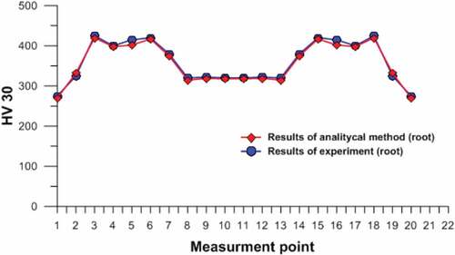
was obtained analytically as shown in Figure (Piekarska et al., Citation2018). The experimental and analytical results for hardness distribution in the weldment for root and face show similar trend as shown in Figures -.
Figure 15. Numerical model of a welded flat plate of S1100QL Steel (Piekarska et al., Citation2018)
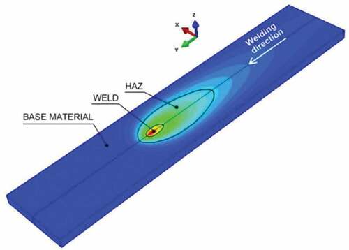
Figure 16. The cross section of weldment and 42 selected Hardness Measurement Points (Piekarska et al., Citation2018)
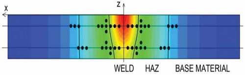
Figure 17. Hardness distribution in the cross section of weldment for face (Piekarska et al., Citation2018)
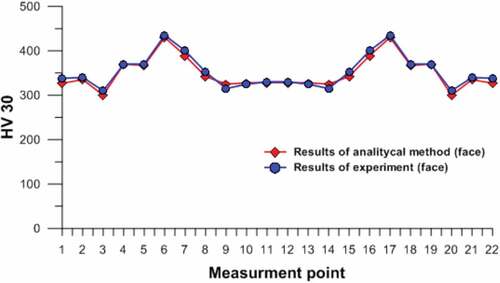
Figure 18. Hardness distribution in the cross section of weldment for root (Piekarska et al., Citation2018)
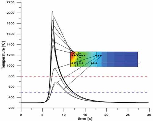
The thermal cycles at different points in the weldment are a key factor in determining the microstructure and properties and can provide clear information on how the welding residual stresses occur in the course of the welding process as shown in Figure (Malik et al., Citation2007).
Figure 19. Thermal cycles measurement points for face (Piekarska et al., Citation2018)
6. Result and discussion
Estimating the carbon Equivalent (CE) value of carbon steels before welding design/procedure will go a long way in determining the preheat/interpass temperature and weldability of the material. Having known this, pertinent welding design can be put in place to prevent weld failure.
The choice of the welding process, optimum primary welding parameters (current, arc voltage, and travel speed) can ensure the estimation of carbon equivalent value of the material in question. The primary cause of cold cracking at the heat affected zone is rapid cooling, a metallurgical transformation triggered by the welding heat. Parallel boundary heat temperature, preheat Initial elevated temperature and can be used to enhance the microstructure for better toughness and tensile strength by slowing down the cooling rate. Additionally, post weld heat treatment influences the mechanical properties after welding before the occurrence of cold cracking as it is the time-dependent martensitic transformation of the microstructure at the heat affected zone. Thick workpiece requires high heat input and shows a slow cooling rate when compared to the thin workpiece. Thin metal coolings rapidly at HAZ as it requires low heat input.
Rosenthal’s equation assumed initial temperature to be at room temperature; this will be modified for boundary heat temperatures in the future research.
7. Conclusion
The heat input of the selected welding process depends on the welding current, voltage, speed and thermal efficiency of the process which in turn affects the cooling rate. However, the cooling rate is also directly affected by parallel boundary heat transient temperatures, the thickness of the weldment, welding speed, post-weld heat treatment, interpass (multipass weld) and preheat temperatures. Thus, to achieve sound and crack free weld quality of carbon steel in the arc-based welding process, appropriate selection of welding process and parameters would produce high sound weld quality in carbon steel weldment.
Optimization of the process and its parameters for sound weld integrity and modified Rosenthal’s equation for temperature distribution with boundary heat would be examined in the future research.
Additional information
Funding
Notes on contributors
Oluwasegun S. Odebiyi
Oluwasegun S. Odebiyi is currently lecturing in the Department of Mechanical Engineering Kampala International University, Uganda. His research areas include Service performance quality and Reliability of weldment, Residual stresses in welded structures, Composite materials development and properties, Finite element analysis, and Metallurgical Engineering. [email protected] [email protected]
Segun M. Adedayo
Segun M. Adedayo, is a professor of Mechanical Engineering in the Department of Mechanical Engineering, University of Ilorin,Nigeria. Prof.S.M.Adedayo’s specific area of interest includes Mechanical testing of engineering materials, Residual stresses in structure, service quality and Reliability of weldment. [email protected] [email protected]
Lawal A. Tunji
Dr. Lawal A. Tunji has a PhD in Civil Engineering with a specialization in Water Resources Engineering from the Universiti Teknologi PETRONAS, Malaysia. He is presently the Head of Department, Civil Engineering, Kampala International University [email protected]
Martins O. Onuorah
Dr. Martins O. Onuorah has a PhD in applied mathematics with a specialization in epidemiological, Ecological and Dynamical system modelling. He is currently a senior lecturer in the Physical Sciences department of the Kampala International University [email protected]
References
- Adedayo, S., Odebiyi, O. S., & Oseni, G. L. (2013). Effect of parallel heating on properties of a welded AISI 8438 steel. Annals of Faculty Engineering Hunedoara-International Journal of Engineering, 321–324. TomeXI, Fascicule3. ISSN 1584-2673.
- Adedayo, S. M., & Momoh, S. O. (2010). Effect of initial elevated metal temperature on mechanical properties of an arc-welded mild steel plate. Indian Journal of Science and Technology, 3(12), 1224–1228. ISSN: ISSN: .
- Asibeluo, I. S., & Emifonye, E. (2015). Effect of arc welding current on the mechanical properties of A36 carbon steel weld joints. International Journal of Mechanical engineering(SSRG-ISME), 2(9), 32–40.
- Balasubramanian, V., Varahamoorthy, R., Ramachandran, C. S., & Muralidhavan, C. (2009). Selection of the welding process for hardfacing on carbon steels based on quantitative and qualitative factors. The International Journal of Advanced Manufacturing Technology, 40, 887–32. doi:10.1007/s00170-008-1406-8
- Boumerzong, Z., Derfouf, C., & Baudin, T. (2010). Effect of welding on microstructure and mechanical properties of an industrial low carbon steel. Engineering. doi:10.4236/eng.2010.27066
- Cao, X., Jahazi, M., Immarigeon, J. P., & Wallace, W. (2006). A review of laser welding techniques for magnesium alloys. Journal of Materials Processing Technology, 171, 188–204. doi:10.1016/j.jmatprotec.2005.06.068
- Chen, B., & Zhu, L. (2015) Analysis on the microstructure and mechanical properties of the welding joint of low alloy structural steel plate by narrow gap MAG. International Conference on Mechatronics, Electronics, Industrial and Control Engineering MEIC, China.
- Cvetkovski, S., Slavkov, D., & Magdes, J. (2003) Welding procedure specification for arc welding of st 52-3N steel plates with covered electrodes. Proceedings of 3rd BMC-2003-Ohrid, Republic of Macedonia.
- Domanski, T., Sapietova, A., & Saga, M. (2017). Application of abaqus software for the modeling of surface progressive hardening. Procedia Engineering, 177, 64–69. Conference in Boston. doi:10.1016/j.proeng.2017.02.184
- Dong, L., Qiu, X., Liu, T., Lu, Z., Fang, F., & Hu, X. (2017). Estimation of cooling rate from 800 °C to 500 °C in the welding of intermediate thickness plates based on FEM Simulation. Journal of Materials Science and Engineering, 7, 258–267.
- Dupunt, J. N., & Marder, A. R. (1995, December). Thermal efficiency of arc welding processes. Welding Research-Supplement, 406–416.
- Dutta, J., & Narndranath, S. (2014, January). Thermochemical analysis of arc welding carbon steel butt Joints: A parametric study. Reference ID, 37, 1–7.
- Etin-Osa, C. E., & Achebo, J. I. (2017). Analysis of optimum butt welded joint for mild steel components using FEM (ANSYS). Advances in Applied Sciences, 2(6), 100–109.
- Goldak, J. A. (2015). Computational welding mechanics. New York,NY: Springer.
- Graville, B. A. (1973, September). Weld cooling rates and heat-affected zone hardness in a carbon steel. Welding Research-Supplement of the Welding Journal, 54, 377–383.
- Hinton, R. W., & Wiswesser, R. K. (2008, November). For unknown grades of carbon and low-alloy steels. Welding Research-Supplement to the Welding Journal, 87, 273–278.
- Khaled, T. (2014). Preheating, interpass and post-weld heat treatment requirements for welding low alloy steels. ANC Report, 6(September), 1–14.
- Khurmi, R. S., & Gupta, J. K. (1997). A textbook of workshop technology manufacturing processes (pp. 287–328). Nirja Constructtion & Development Co. Ltd.
- Kumar, R., Anja, H. K., & Saxena, R. K. (2014). Experimental determination of cooling rate and its effect on microhardness in submerged arc welding of mild steel plate(Grade C-25 as per IS1570). Journal of Materials Science and Engineering, 3(2). doi:10.4172/2169-0022.1000138
- Kumar, R., Arya, H. K., & Saxena, R. K. (2014). Effect of cooling rate on microstructure of saw welded mild steel plate (Grade C 25 as per IS 1570). International Journal of Modern Engineering Research, 4(1), 222–228.
- Kumar, R., & Kumar, S. (2014). Study of mechanical properties in mild steel using metal inert gas welding(MIG). International Journal of Research in Engineering and Technology, 3(4), 751–756 ISSN:.
- Kumarkhamari, B., Sahu, P. K., & Biswal, B. B. (2018). Microstructure analysis of arc welded mild steel plate. IOP Conf.Series: Materials Science and Engineering, 377. doi:10.1088/1757-899x/377/1/0/2049
- Lecoanet, A., Ivey, D. G., & Henein, H. (2014). Simulation of TEMPERATUREPROFILE during welding with COMSOL multiphysics software using Rosenthal’s approach. Excerpt from the Proceedings of the 2014 COMSOL.
- Liskevych, O., & Scotti, A. (2015). Journal of materials processing technology determination of the gross heat input in arc welding. Journal of Materials Processing Technology, 225, 139–150. doi:10.1016/j.jmatprotec.2015.06.005
- Malik, M. A., Qureshi, M. E., & Dar, N. U. (2007). Numerical simulation of arc welding investigation of various process and heat Source parameters. Failure of Engineering Materials and Structures, 30, 127–142.
- Mohammed, R. A., Abdulwahab, M., & Dauda, E. T. (2013). Properties evaluation of shielded metal arc welded medium carbon steel materials. International Journal of Innovative Research in Science Engineering and Technology, 2(8):2013. ISSN: .
- Mousavi, S. A. A. A., & Kelishami, A. R. (2008). Experimental and numerical analysis of the friction welding process for the 4340 steel and mild steel combinations. Welding Journal, 87(July), 178s–186s.
- Murugan, S., Kumar, P. V., Gill, T. P. S., Raj, B., & Bose, M. S. C. (1999). Numerical modelling and experimental determination of temperature distribution during manual metal arc welding. Science and Technology of Welding and Joining, 4(6), 357–364.
- Nassef, G. A., & Abdallah, I. A. (2012). Numerical modeling of heat transfer and fluid flow in keyhole plasma arc welding of dissimilar steel joints. International Journal of Engineering Science and Technology, 4(2), 506–518. ISSN:0975-5462ISSN:.
- Nunes, A. C. (1983, June). An extended rosenthal weld model. Welding Research Supplement 62(6), 169–170.
- Pamnani, R., Vasudevan, M., Jayakumar, T., Vasantharaja, P., & Ganesh, K. C. (2016). Numerical simulation and experimental validation of arc welding of DMR-249A steel. Defence Technology, 12(4), 305–315.
- Parthiban, K., Shanmugam, N. S., & Shankara, K. (2018). Experimental and numerical investigation of charpy impact test of spin arc welded C1018 plates. IOP Conference Series: Materials Science and Engineering, 455(012069). doi:10.1088/1757-899x/455/1/012069
- Pépe, B. N., Egerland, S., Colegrove, P. A., & Yapp, D. (2011). Measuring the process efficiency of controlled gas metal arc welding processes. Science and Technology of Welding & Joining, 16(5), 412–417.
- Piekarska, W., & Dorota, G. K. (2016). Prediction of structure and mechanical properties of welded joints using analytical methods. Procedia Engineering, 136, 82–87. doi:10.1016/j.proeng.2016.01.178
- Piekarska, W., Saga, M., Kroliszewka, D. G., Domanski, T., & Kopaj, P. (2018). Application of analytical methods for determination of hardness distribution in a welded joint made of S1100QLSteel. Matecweb of Conferences, 157(02041). doi:10.1051/matecconf/201815702041
- Poorhaydari, K., Patchett, B. M., & Ivey, D. G. (2005). Estimation of cooling rate in the welding of plates with intermediate thickness. Welding Journal, 84(10), 149–155.
- Prasad, K., & DWivedi, D. K. (2008). Some Investigations on microstructure and mechanical properties of submerged arc welded HSLA steel joints. The International Journal of Advanced Manufacturing Technology, 36, 475–483. doi:10.1007/s0v/70-006-0855-1
- Prasanna, P., Rao, B. S., & Rao, G. K. M. (2010). Experimental and Numerical evaluation of friction stir welds of Aa6061-T6 aluminium alloy. ARPN Journal of Engineering and Applied Sciences, 5(6), 1–18.
- Ramasamy, N., & Kathiravan, R. (2017). Influence of welding parameters on mechanical properties of high strength low carbon steel of submerged arc butt welds. Indian Jounal of Science Reseach, 14(1):228–235. ISSN:.
- Rizvi, S. A., Tewari, S. P., & Ali, W. (2013). Weldability of steels and its alloys under different conditions - A review. International Journal of Science, Engineering and Technology Research (IJSETR), 2(3), 539–550.
- Roblendo, D. M., Alberto, J., & Enrique, J. (2011). Development of a welding procedure for MIL A46100 Armor steel joints gas metal arc welding. Dyna, 78(168):65–71. ISSN.
- Samardzic, I., Croric, A., & Dunder, M. (2016). Weldability investigation of fine-grained S1100QL Steel. Metalurgija, 3(55), 453–456.
- Samir, M. (2015). Investigation on effect of heat input on cooling rate and mechanical property (Hardness) of mild steel weld joint by MMAW Process. International Journal of Modern Engineering Research, 5(3), 34–41.
- Sarkar, A., Rai, R. N., & Saha, S. C. (2015). A study of parametric effects on thermal profile of submerged arc welding process. Journal of Naval Architecture and Marine Engineering. doi:10.3329/Jname.v12i1.22670
- Scott Funderburk, R. (1998). The importance of interpass temperature. Welding Innovation, XV(1), 1–2.
- Singh, A., Singh, J., & Kumar, R. (2016). A study of microstructure and hardness in En 31 steel and mild steel welded joints using TIG welding. International Journal of Engineering Science and Computing, 6(10), 2849–2854.
- Singh, R. P. (2012). Parametric effect on mechanical properties in submerged arc welding process-A review. International Journal of Engineering Science and Technology, 4(2), 747–757ISSN:.
- Slezak, T., & Sniezek, L. (2014). Fatigue properties and cracking of high strenght steel S1 100QL welding joints. Key Engineering Materials, 598(237–242). doi:10.4028/www.scientific.net/KEM.598.237
- Sloderbach, Z., & Pajak, J. (2015). Determination of ranges of components of the heat affected zone including changes of structure. Archives of Metallurgy and Materials, 60(4). doi:10.515/amm-2015-0421
- Soy, U., Lyibilgin, O., Findik, F., Oz, C., & Kiyan, Y. (2011). Determination of welding parameters for shielded metal arc welding. Scientific Research and Essays, 6(15), 3153–3260. doi:10.5897/SRE10.1073
- Stenbacka, N., Choquet, I., & Hurtig, K. (2012). IIW commission IV-XII-SG212 intermediate meeting review of arc efficiency values for gas tungsten arc welding. IIW Commission Berlin Germany, 1–21.
- Sykora, A. J. (2015, June). Finite element analysis of heat distribution and cooling in welding (Ph.D. Thesis). Charles Darwin University, School of Engineering and Information Technology, Faculty of Education, Health, Science and the Environment.
- Tahir, A. M., Lair, N. A. M., & Wei, F. J. (2018). Investigation on mechanical properties of welded materials under different types of welding filler(Shielded metal arc welding). AIP Conference Proceedings 1958, Selangor, Malaysia, 020003. doi:10.1063/1.5034534.
- Talabi, S. I., Owolabi, O. B., Adebisi, J. A., & Yahaya, I. (2014). Effect of welding variables on mechanical properties of low carbon steel welded joints. Advances in Production Engineering & Management, 9(4), 181–186. ISSN. doi:10.14743/apem2014.4186
- Tsuei, H.-E. (2000). Analysis and modeling of weld metal mechanical properties in flux cored arc welded steels (Doctor of Philosophy Thesis). Department of Materials Engineering University of Wollongong, 200. Retrieved from http://ro.uow.edu.au/theses/1484