
 ?Mathematical formulae have been encoded as MathML and are displayed in this HTML version using MathJax in order to improve their display. Uncheck the box to turn MathJax off. This feature requires Javascript. Click on a formula to zoom.
Abstract
Enhancement of heat transfer in solar air heater systems using corrugations has the dual benefit of enhanced heat transfer area and enhanced flow turbulence. This work presents two-dimensional computational fluid dynamics (CFD) analysis to evaluate the effect of discrete triangle wave corrugations on the absorber plate for different flow Reynolds numbers of 6000–24000. The geometric parameters of corrugation such as the non-dimensional amplitude (A = 0.025, 0.05 and 0.1) and non-dimensional wavelength (WL = 0.113, 0.226 and 0.453) are varied to establish the thermo-hydraulic performance. The CFD results reveal that the presence of discrete triangle wave corrugations significantly affect the flow structure near the absorber surface and exhibit enhanced fluid turbulence levels. The highest increase in the Nusselt number is found to be about 2.082 times higher than that of the smooth duct for A = 0.1 and WL = 0.453 at Re = 6000. The maximum rise in friction factor is about 2.568 times that of the smooth duct at Re = 6000 for the configuration of WL = 0.113 and A = 0.1. The configuration having A = 0.1 and WL = 0.453 can be particularly useful for lower flow rate requirements and exhibits the highest thermal enhancement factor (TEF) of about 1.612 at Re = 6000 among all the configurations considered in the present study. However, the configuration having A = 0.05 and WL = 0.453 provides a relatively steady TEF performance for a wider range of flow rates with a maximum TEF of 1.473 at Re = 12,000.
PUBLIC INTEREST STATEMENT
Owing to ever-growing demand for energy due to increased urbanization, the rate at which fossil fuels are being used for energy generation is at an alarmingly higher rate, which could lead to its faster depletion. As an alternative, the use of solar energy could reduce the burden on fossil fuels for energy generation, and it is also freely available. Many applications in engineering such as drying of agricultural products, timber and so on need hot air supply, which could be provided using freely available solar energy. Solar air heaters are specifically used for generating hot air using solar thermal energy. However, they suffer from poor thermal characteristics and need attention for enhancing their heat transfer capability. This work introduces a specially designed absorber plate to improve the heat transfer capability of solar air heaters.
1. Introduction
There has been a rising demand for energy due to increased urbanisation and industrial expansion, which has led to rapid utilization of fossil fuels that may not last forever. Most of the existing technologies currently used in many industrial, healthcare, military and transport sectors make use of fossil fuels, and there is a need to develop renewable energy technologies to spare fossil fuels for non-critical applications to extend the reserves of fossil fuels. As a result, current research trends are shifting toward sustainable energy, and solar energy, in particular, is emerging as one of the vital means of meeting future energy demands. Solar thermal energy and photovoltaic energy are two most common uses of solar energy. In particular, harvesting solar thermal energy requires specific solar radiation collection devices called solar collectors. Solar collectors can be of flat plate design or concentrating collector design. Flat plate collectors mainly find their use in low-temperature heating requirements such as drying and space heating and owing to their simplicity in design that offers lower maintenance and further makes them attractive for these applications.
Solar drying is one of the common uses of solar thermal energy that makes use of flat plate solar air heater systems. Unfortunately, due to substantial heat energy losses from the absorber plate combined with lower heat transfer capability of air, they often have poor thermal efficiency. As a result, the development of an effective flat plate solar air heater is critical. Thermo-hydraulic properties such as heat transfer coefficient and pressure drop are the primary parameters on which the thermal performance of the solar air heating devices is optimized. Among the various passive heat transfer enhancement techniques, the use of ribs also called turbulators has been widely adopted owing to their effectiveness. Ribs of various cross-sectional geometries have been shown to significantly influence the thermal performance of solar air heaters. Special designs such as arc-shaped ribs, spherical ribs, converging–diverging ribs, twisted ribs, and winglets have also been reported, which are found to improve heat transfer performance considerably. However, they are also associated with higher frictional losses in the flow domain as a result of flow constriction. Each design has been shown to consist of its own limitations in terms of the useful range of operating flow rate within which its use is justified to keep the pressure drop within acceptable limits. Hence, there have been constant efforts in researching the best design that provides higher heat transfer with minimal pressure drop penalty.
Bhagoria et al. (Citation2002) investigated the effect of wedge-shaped ribs at different wedge angles and relative roughness for a rectangular solar air heater duct for the Reynolds number range of 3000–18000. They carried out experimental analysis for different relative roughness heights (0.015–0.033), relative roughness pitches (7.57–12.12) and wedge angles (8°, 10°, 12° and 15°). The friction factor increased by 5.3 times, while the Nusselt number increased by 2.4 times as compared to the smooth duct. The wedge angle of 10° is found to exhibit the highest increase in heat transfer owing to the reduced size of the flow recirculation zone behind the ribs. Ebrahim Momin et al. (Citation2002) experimentally studied the effects of a V-Shaped rib for the Reynolds number range of 2500–18000 and different flow angles of attack of 30°–90°. The thermo-hydraulic performance is shown to increase with increasing angle of attack of flow and relative roughness height until 60° at which the largest increase in the Nusselt number and friction factor is reported (2.30 and 2.83 times, respectively, that of a smooth duct). The V-shaped arrangement increases the interaction effects between the main and the secondary flows, which increases the heat transfer. Jin et al. (Citation2019) used multiple V-shaped ribs using the computational fluid dynamics (CFD) methodology to further enhance the overall thermal performance and achieved a maximum thermo-hydraulic performance factor of about 2.35. The use of multiple V-ribs significantly increases the flow turbulence by introducing secondary flows at several locations on the absorber plate. In another study, Sharma et al. (Citation2019) have shown that the pentagonal rib geometry can significantly suppress hotspot regions behind the ribs. They investigated the effect of different chamfering angles (0°–20°) and non-dimensional rib heights (6–12) on the overall performance. The chamfering angle of 5° is found to improve heat energy transfer over the entire inter-rib region in comparison to the square rib region. S. Kumar & Saini (Citation2009) numerically evaluated the efficacy of circular wire in arc-shaped geometry using the Renormalization-Group (RNG) k–ϵ turbulence model. The thermal enhancement ratio is obtained as 1.7 with a non-dimensional arc angle of 0.333 and a relative height of 0.0426. Jaurker et al. (Citation2006) examined the rib–groove combination effect on thermal performance for varying relative heights (0.0181–0.0363), pitches (4.5–10.0) and groove positions (0.3–0.7). The formation of vortices near the groove is found to further rise heat energy transfer as compared to plain ribs. The Nusselt number and friction factor increased to the extent of 2.7 times and 3.6 times that of the smooth duct, respectively. The peak heat transfer is exhibited for the non-dimensional groove distance of 0.4. Azad et al. (Citation2021) analysed the effect of discrete symmetrical arc rib geometry to enhance the thermo-hydraulic performance of a solar air heater. The parameters that were investigated were non-dimensional gap distances of 2, 3, 4, and 5, a non-dimensional height of 0.045, a relative pitch of 10 and the flow inclination of 30° for the Reynolds number range of 3000–14000. The effective performance is seen to be much higher for a discrete arc rib as compared to a V-rib with a maximum value of 1.68. The arrangement of arc-shape parallel wire ribs has been shown by Saini & Saini (Citation2008) to significantly improve the heat transfer by 3.80 times for a non-dimensional arc angle of 0.3333 with a relatively lower friction factor penalty.
A combination of different rib geometries can be beneficial for tapping the benefits of different geometries as shown by Alfarawi and Bodalal (Citation2017), where a hybrid configuration of semi-circular and rectangular ribs was used in a rectangular duct for high Reynolds number conditions. The Nusselt number and friction factor ratio were found to be varying from 1.3 to 2.14 and 1.8 to 4.2, respectively, with a slight improvement in the efficiency index for combined ribs. Gill et al. (Citation2021) put forward a computational and experimental examination of a hybrid broken arc and staggered rib for the Reynolds number range of 2000–16000 by varying different geometric parameters such as the gap distance, the position of the staggered rib, the angle of the arc, etc. The analysis shows that the hybrid design augments the friction factor as well as heat transfer by 2.57 and 3.16 times, respectively. Sahu et al. (Citation2019) have shown that the use of combined semi-circular and triangular ribs in a rectangular channel provides augmented effective thermal performance as compared to either of the individual rib geometry. They carried out numerical analysis using the shear stress transport (SST) k–w turbulence model.
Special turbulator designs such as discretely placed truncated prismatic ribs obtained by tapering the square ribs from both sides to the centre (Sharma et al., Citation2018) are shown to augment heat transfer considerably by way of turbulence as well as surface area enhancement. The ribs are shown to suppress the formation of hot spots that are characterized by poor heat transfer. The ribs are shown to provide better thermal performance than the square ribs with a nearly 25.15% increase in the Nusselt number and about 54.65% reduction in the friction factor. Barik et al. (Citation2021) made use of a T-shaped rib that improves heat transfer by about 191% owing to intense turbulence levels induced in the flow. A novel twisted rib has been shown by A. Kumar & Layek (Citation2018) to provide increased heat transfer and friction factor as high as 2.58 and 1.78 times than the smooth duct, respectively. Manjunath et al. (Citation2017) have shown that spherical turbulence generators are very much beneficial in heat transfer augmentation owing to the dual benefit of turbulence and heat transfer area enhancement. The influence of pitch and diameter for a fixed transfer pitch is evaluated under simulated solar heat flux conditions using numerical analysis. The geometry of the sphere is found to play an immense role in providing augmented turbulence levels with a limiting friction factor penalty. A maximum Nusselt number enhancement of up to 2.52 times over the smooth duct is reported for a relative pitch of 3 and a diameter of 0.025 m. In another experimental study, Maithani et al. (Citation2020) used spherical turbulators having different ranges of design and operating parameters and found that the efficiency factor reached as high as 2.98 at Re = 10,500. Prakash & Saini (Citation2019) combined the spherical and inclined rib protrusions to tap high turbulence and low pressure drop characteristics of spherical turbulator and achieved a rise in Nusselt number of 2.88 times. Combined use of vortex generators such as delta winglets with transverse ribs as suggested by Zhao et al. (Citation2021) has received attention in the recent past owing to the efficacy of winglets in providing longitudinal vortices that sustain forrelatively longer flow lengths in comparison to the transverse vortices generated by the ribs. They made use of continuous and truncate dribs at different flow attack angles. The heat transfer improvement for the combined case is found to be about 39.4% higher than that of plan vortex generators.
Novel turbulence generators such as anchor-shaped inserts (Chamoli et al., Citation2018) and tori inserts (Chamoli et al., Citation2021) have been shown to provide significant flow turbulence and heat transfer improvement in the area of circular tube heat exchangers. The shape and orientation of these geometries have been shown to significantly influence the heat transfer and pressure drop characteristics and are found to generate longitudinal vortices in the pipe flow. Similar vortices can be generated using rectangular winglet pairs on the absorber plate of the solar air heater to augment the flow turbulence as shown by Dezan et al. (Citation2020). They made use of the non-periodic arrangement of rectangular winglet pairs to determine the optimal parameters of flow attack angle and winglet size. They found that the first rows have a significant impact on pressure drop than the subsequent rows. The arrangement of winglets that create flow-up patterns of vortices is found to generate stronger flow turbulence as compared to the flow-down arrangement. The use of perforation on winglets (Skullong et al., Citation2018) is found to provide significant TEF performance in the range of 1.78–2.01 by introducing flow impingement jets through the perforations, which augment heat transfer from the heated plate. Punched winglets (Promvonge et al., Citation2021) have been shown to reduce friction loss by reducing the recirculation zone on the backside of the winglets.
Combined use of delta winglets with V-shaped ribs (Zhao et al., Citation2021) has been shown to augment heat transfer by nearly 39.4% when only one pair of winglets is used with a maximum TEF of around 1.43 at Re = 4000. Thus, as compared to transverse or inclined ribs, the winglets exhibit higher turbulence augmentation by generating longitudinal vortices that exist for a relatively long distance in the flow direction as compared to transverse vortices generated by the ribs. Further, ribs and vortex generators of various designs majorly focus on turbulence augmentation to achieve a higher heat transfer rate. Heat transfer enhancement through the enhanced surface area in addition to enhanced flow turbulence using corrugations on the absorber plate can be an effective technique. However, very few studies have explored this option using V-corrugations, Sinewave and cross corrugations on the absorber plate, usually with double pass arrangements for airflow. Limited studies on the use of corrugations have shown that a properly designed corrugation not only provides higher turbulence mixing of hot and cold airstreams just like the rib turbulators and vortex generatorsbut also augments the area for heat transfer. Sinusoidal corrugations (Manjunath et al., Citation2018) have been reported to increase heat transfer efficiency by about 12.5% with a surface area enhancement of 1.6%–45% in comparison to smooth surfaces. The study made use of different corrugation wavelengths and amplitudes in the range of 0.06–0.16 m and 0.0075–0.02 m, respectively. It is shown that the effective heat transfer is poor at higher flow rates due to increased friction factor penalty owing to higher flow obstruction effects caused by the corrugation surfaces. The use of sinewave corrugations with air-jet impingement (Aboghrara et al., Citation2017) has been shown to further increase the thermal performance up to 14% with an about 3°C rise in temperature over that of the plain duct. Lin et al. (Citation2006) made use of sinewave corrugations on both the top and bottom plates resulting in a cross-corrugated arrangement, which is found to exhibit much superior performance than the smooth duct with about 17% higher thermal efficiency. The use of a lower external recycle ratio (Ho et al., Citation2021) can be advantageous in efficiently transferring the heat energy to the airstream, achieving a thermal efficiency rise of 1.33 times that of a single-pass flat plate system.
El-Sebaii et al. (Citation2011) made use of V-corrugations in a double-pass arrangement and concluded that the V-corrugations provide about 14% rise in efficiency over that of smooth plates in a double-pass arrangement. However, for a single-pass arrangement, the rise in thermal efficiency is about 12%, which is experimentally found to be sufficient enough to generate a good temperature rise in the airstream to achieve crop drying (Karim & Hawlader, Citation2006). V-corrugations with double-pass and recycle arrangements (Ho et al., Citation2016) have been shown to further improve the thermal efficiency by 137.6%. However, the pressure drop penalty is found to be large at higher flow rates of air. In another study, El Ferouali et al. (Citation2018) made use of mathematical modelling to predict the thermal performance of V-corrugations over flat plate solar air heaters and found that the thermal efficiency increased by 21.64%. The recycle ratio is found to have a considerable influence on thermal performance as reported by Ho et al. (Citation2017). An innovative combination of V-corrugations on the absorber plate with twisted tape inserts (Farhan et al., Citation2021) shows an improvement in the thermo-hydraulic efficiency by 17% as compared to the twisted tape alone. The V-corrugations are provided in line with the flow and the tapes are placed within the narrow passage of each corrugation, which provides the combined effect of increased turbulence and heat transfer area. Generation of a roughened surface using the shot blasting method on V-corrugations of the absorber plate provides additional flow turbulence, which enhances heat transfer and eliminates dead zones that may exist in V-corners (Poongavanam et al., Citation2018).
Further, transverse circular ribs (Gupta et al., Citation1993) are straightforward to use as they are readily available in standard sizes in the form of wires and have been shown to perform well in terms of heat transfer. However, they exhibit hot spots at the rib corner regions, which is detrimental for heat transfer. This limitation could be overcome by the use of a quarter circle rib (Mahanand & Senapati, Citation2021). Some novel turbulence promotors such as V-shaped flapped baffles combined with chamfered grooves (Promvonge & Skullong, Citation2021) have been shown to produce a TEF of 2.68, which is significantly high in comparison to most of the other existing designs, although the design is very complex in nature.
Thus, it is clearly seen from the literature that turbulence enhancement in the airflow using ribs of various shapes and arrangement patterns can be very beneficial in achieving overall thermal performance augmentation. The combined augmentation of surface area and flow turbulence around the enhanced heat transfer area using corrugations can further improve thermal performance. A recent investigation on inclined sinusoidal corrugations also called ripple surface (Dong et al., Citation2021) has been shown to significantly enhance heat transfer by about 3.38 times that of the smooth duct, which provides the combined effect of enhanced heat transfer area and enhanced turbulence in the flow. However, despite these advantages of corrugations, there has been a dearth of research in developing better corrugation designs and very limited works have been reported on the use of cross corrugations, sinusoidal corrugations and V-corrugations on the absorber plate. A major focus among all these limited studies has been on the use of V-corrugations and has been either experimental or analytical. There has been very limited study on the use of the numerical methodology in performance enhancement investigations using corrugations, which can bring out better insights into the flow physics that influence heat transfer and pressure drop characteristics in the corrugated solar air heater system. Since the major drawback of any of the corrugations used in the literature is its increased pressure drop penalty at higher flow rates of air, there is a need to develop better designs of corrugations to achieve better performance. This limitation of corrugation needs to be further investigated in order to further improve the effective thermal performance using corrugations that could be done effectively by using the numerical simulation methodology, which helps to bring out the flow structure under varying flow and geometric parameters. Unfortunately, there has been very limited research on corrugations, which served as the motivation for this study. Further, it is observed from the literature review that the corrugations used in the past studies are continuous in nature, which could be the cause for the higher pressure drop penalty. Therefore, there is a need to evaluate the performance using discontinuous or discrete corrugations to determine the extent of effective heat transfer enhancement. The present work aims to investigate the influence of discontinuous or discrete triangle wave corrugations on the absorber plate. The triangular geometry is chosen for the corrugations due to the fact that the triangular ribs (Alfarawi and Bodalal, Citation2017; Sahu et al., Citation2019) have been shown to provide better thermohydraulic performance as compared to the semi-circular (Yadav et al., Citation2021) as well as rectangular geometry. Since the study makes use of discontinuous corrugations, the obstruction to the airflow could be limited depending on the relative distance between the corrugations besides achieving increased flow turbulence and heat transfer.
The objective of this work is to
determine the efficacy of discrete triangle wave corrugations using the CFD methodology and establish the heat transfer and friction factor characteristics for different flow Reynolds numbers. The influence of pitch distance, wavelength and amplitude of corrugation will be brought out using CFD analysis.
2. Computational fluid dynamics (CFD) methodology
This section describes the geometric details of various configurations of triangle wave corrugations used in the analysis, boundary conditions, numerical schemes, grid independence test and validation of CFD results. The analysis makes use of the CFD methodology in which the simulation study is carried out using the ANSYS Fluent software tool. The CFD analysis is used for evaluating the effect of different geometric parameters of triangle wave corrugations on the overall thermal performance of air heaters. The validation of CFD results is carried out using the experimental results of Gupta et al. (Citation1993).
2.1. Geometry details
The study involves a two-dimensional numerical analysis of flow and heat transfer through a rectangular duct solar air heater system, as shown in ). The flow domain considered for the numerical analysis consists of three sections named as inlet section, test section and exit section, each having a length of 0.275 m, 0.32 m and 0.14 m, respectively. The inlet and exit section lengths are fixed as per the ASHRAE standards (Bhagoria et al., Citation2002), which suggests a minimum entrance length for the turbulent flow to develop fully and is given by 5 . For the exit section, the length is determined using 2.5
. The height (H) and width (W) of the duct are fixed as 0.15 m and 0.02 m, respectively, which corresponds to a hydraulic diameter of 0.03529 m. Discrete triangle wave corrugations are provided on the absorber plate, as shown in ).,
Figure 1. Geometric details of the two-dimensional computational domain of a solar air heater (a) with a smooth absorber plate and (b) with triangle wave corrugations on the absorber plate.
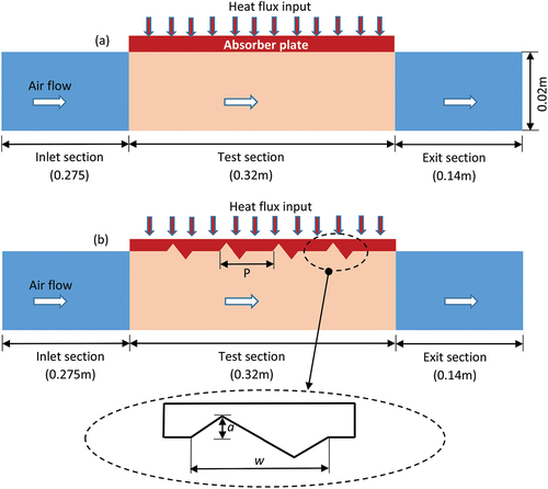
The corrugation geometry can be varied using the amplitude and wavelength. Too high amplitude leads to greater protrusion into the airflow, which could adversely affect the pressure drop, while a too large wavelength could reduce the number of corrugations, thereby diminishing its influence on thermal performance. Hence, the amplitude is varied moderately as 0.0005 m, 0.001 m and 0.002 m, which is basically about 2.5%, 5% and 10% of the duct height “H”. The wavelength is varied as 0.004 m, 0.008 m and 0.016 m, respectively, which is within 5% of the test section length used in the analysis. The number of corrugations on the absorber plate is decided using the pitch parameter, which is varied as 0.02 m, 0.03 m and 0.04 m, which is within 12.5% of test section length. The amplitude is non-dimensionalized with respect to the duct height (A = a/H), while the wavelength is non-dimensionalized with respect to the length of the test section (WL = w/L). The various configurations used in the study are shown in .
Table 1. Different geometric configurations of discrete triangle wave corrugations
2.2. Boundary conditions and solver settings
The air velocity ranging between 2.85 m/s and 11.23 m/s, which relates to the Reynolds number range of 6000–24000, is specified at the duct inlet. The Reynolds number is varied between 6000 and 24,000 based on the observations of previous published works (Bezbaruah et al., Citation2021; Bhuvad et al., Citation2021; Dong et al., Citation2021; Manjunath et al., Citation2018, Citation2019; Patel et al., Citation2021; Promvonge et al., Citation2021; Promvonge & Skullong, Citation2021; Yadav et al., Citation2021; Zhao et al., Citation2021), which used similar range of airflow rates within which a solar air heater exhibited its peak overall thermal performance. The air makes its entry to the duct at a temperature of 308 K. Since the air exits to the atmosphere through the duct exit, atmospheric pressure of 101,325 Pa is applied at the duct outlet. Heating of the absorber plate is achieved by applying a constant heat flux of 800 W/m2, and no-slip conditions are effected at the solid–fluid interface along with impermeable conditions. All other duct boundary surfaces are assumed to be insulated for any heat loss to surroundings. The analysis is conducted using the ANSYS Fluent software tool, and coupled solver is adopted in the simulation study to achieve better convergence. The SIMPLE algorithm (Gill et al., Citation2021) is applied for pressure-velocity coupling, and second-order upwind schemes are used for the discretisation of momentum, turbulence and energy equations for higher-order accuracy. The RNG k–ϵ turbulence model with enhanced wall treatment for near-wall modelling is used for flow turbulence modelling, which is found to predict numerical results in close agreement with the experimental solution for solar air heater studies involving flow turbulence promoting devices (Alfarawi and Bodalal, Citation2017; Gill et al., Citation2021; Jin et al., Citation2019; S. Kumar & Saini, Citation2009). The wall Y+ is maintained close to 1 to resolve the boundary layer region, and the residuals are set as 10−6 for continuity momentum and turbulence equations and 10−8 for the energy equation to affect the convergence.
2.3. Governing equations
The governing equations used in the simulation consists of two-dimensional equations of continuity, momentum, turbulence and energy. These equations are discretized using the finite volume method (FVM) by the software tool using the above-specified numerical schemes that are subsequently solved in the form of linear simultaneous equations using matrix solution techniques. The following are the Reynolds averaged Navier–Stokes (RANS) equations used in the analysis.
Continuity equation:
Momentum equation:
Energy equation:
The RNG k–ε turbulence model:
The eddy viscosity is given by
The following are the constant values (Zhao et al., Citation2021) used in the above equations:
C1є = 1.42, C2є = 1.68 and Cµ = 0.0845. Also, ,
, β = 0.012,
.
2.4. Validation of CFD results with experimental correlations
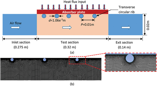
In the present study, in order to carry out the validation of CFD model used in the analysis, the experimental results of Gupta et al. (Citation1993) are utilized, wherein transverse circular ribs are used on the absorber plate. The CFD results are produced for the same circular rib configuration used in their experimental work, which are then compared with their experimental results using the correlations reported in their study. Upon validation of CFD results, the circular ribs in the CFD model are replaced by the triangle wave corrugations for further parametric numerical analysis. The geometric details of duct with circular rib used by Gupta et al. (Citation1993) are shown in ). The boundary conditions specified for the duct with circular ribs are exactly the same as explained in Section 2.2. The meshing of the computational domain is conducted using the ANSYS mesher tool. The mesh of the CFD domain is shown in ), where quadrilateral elements are used. Finer elements are provided near the wall region and around the ribs to capture the flow gradients properly. The wall Y+ is maintained close to 1 to resolve the boundary layer region. The number of grids in the domain is fixed based on the grid independence test. The grid test is carried out for different grid numbers in the flow domain, and the Nusselt number and friction factor are noted for each of the grid numbers for Re = 15,000, as shown in .
Table 2. Results of the grid independence test
Figure 2. (a) Geometric details of the solar air heater duct with circular ribs on the absorber plate (Gupta et al., Citation1993) and (b) meshing of the computational domain with circular ribs.
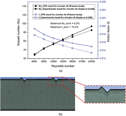
The grid numbers are varied so as to ensure that the number of grids are almost doubled every time in order to obtain a distinct variation in Nusselt number for all the grid sizes. It is seen that the Nusselt number and friction factor variation is less than 0.5% even after increasing the grid number from 305,127 to 701,825. Hence, the grid number 305,127 is chosen to be optimum, beyond which the CFD results predicted by the CFD model used in the analysis are independent of the grid number in the computational domain. From ), it is also seen that the CFD results obtained for the circular rib are in close agreement with those of the experimental results of Gupta et al. (Citation1993), which are determined using the correlation given below. The maximum deviation for the Nusselt number is about 8.3%, while for friction factor, it is about 10.4%. Hence, the CFD model used in the present analysis can be used further for parametric analysis to evaluate the effect of triangular wave corrugations on the thermal performance of solar air heaters by replacing the circular ribs by the corrugations. Similar meshing techniques are used to mesh the air heater domain with triangle wave corrugation, as shown in ).
Figure 3. (a) Validation of CFD results against that of experimental results ofGupta et al. (Citation1993) and (b) meshing details of the air heater duct with discrete triangle wave corrugations.
where the roughness height is given by.
3. Results and discussions
A two-dimensional CFD analysis is carried out to evaluate the efficacy of discretely placed V-corrugations on the thermal and flow characteristics of solar air heaters. The main focus of analysis is to investigate the effect of various geometric parameters of corrugation such as (i) the corrugation pitch, (ii) corrugation amplitude and (iii) corrugation wavelength for different flow rates of air, which corresponds to the flow Reynolds number range of 6000–24000.
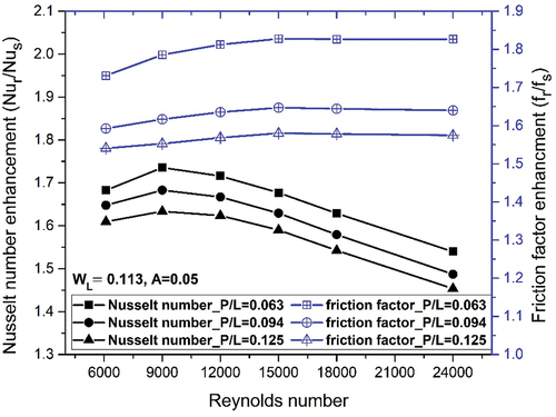
3.1. Influence of corrugation pitch
The corrugation pitch determines the number of corrugations present on the absorber plate and is found to have considerable influence on the heat transfer and pressure drop in the airflow through the duct, as seen in . The non-dimensional pitch is varied as 0.063, 0.094 and 0.125 for a fixed non-dimensional wavelength and amplitudes of 0.113 and 0.05, respectively, for different flow rates of air. shows that the enhancement in the Nusselt number is considerably higher as compared to the smooth duct due to the presence of corrugations on the absorber plate, which leads to increased heat transfer to the surrounding airstream. The Nusselt number for the smooth duct is determined using the well-known Dittus–Boelter correlation (Bhagoria et al., Citation2002) under fluid heating conditions as given below.
Figure 4. Comparison of the Nusselt number and friction factor augmentation for varying pitches and flow Reynolds numbers for WL = 0.113 and A = 0.05.
The Nusselt number for the duct with corrugations is determined using
where .
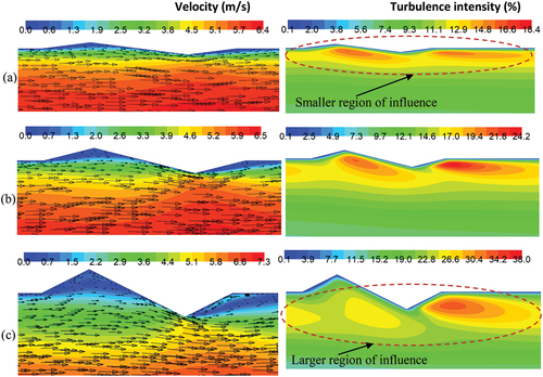
The improvement in heat transfer can be attributed to the presence of considerable flow disturbances induced by the corrugations that enhance flow mixing near the heated absorber plate. In addition, the induced flow disturbances interrupt the boundary layer formation on the corrugation surface, which improves heat energy interaction between the absorber plate and airstream. This is clearly seen by the velocity contour plot in ), which shows the presence of flow velocity variation around each corrugation. A closer look into the flow field around the corrugation with the help of the velocity vector plot reveals that the presence of corrugation interrupts the incoming flow through flow impingement and flow separation, as a consequence of which flow recirculation zones are formed on either side of the corrugation, as seen in ). The incoming airstream impinges on the lower protruding part of the corrugation and deflects partly into the main flow and partly into the crest region. It can be seen from the vector plot that the trough region of the corrugation protrudes downwards into the flow and encounters relatively fast moving airstream, which causes the flow impingement effect. The deflected flow glides down the corrugation surface and creates a scouring effect, which improves heat transfer from the corrugation surface. Further, as the flow glides down the corrugation surface, it undergoes flow separation at the lower tip of the corrugation, resulting in the formation of a recirculation region behind the trough region of corrugation, as seen in ).
Figure 5. Insight into (a) flow structure and (b) turbulence intensity distribution in the airflow around the corrugations.
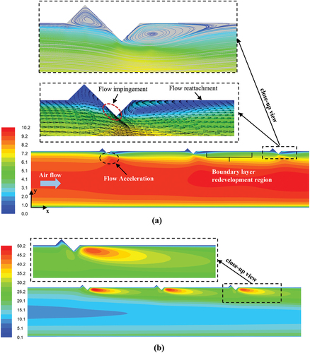
The separated flow is found to reattach with the absorber plate at some distance in the downstream side of the corrugation where the boundary layer region is seen to redevelop, as shown in ). The separated flow and recirculation flow are seen to interact in the downstream region, causing rigorous mixing of airstream, which enhances fluid turbulence levels, leading to increased heat energy exchange within the fluid. This is evidenced by the presence of higher turbulence intensity, as shown by the contour plot of turbulence intensity in ). The turbulence intensity is seen to be at higher levels for a relatively larger distance on the downstream side of corrugations. The part of the deflected flow that moves upwards into the crest region is found to create another recirculation region, as seen in ). The size of this recirculation zone and its subsequent impact on flow and heat transfer depend on the amplitude and wavelength of corrugation. The flow streamlines depicted in ) clearly reveal the formation of recirculation zones on either side of the corrugation. It is interesting to see that the size of the recirculation zone on the upstream side is relatively smaller as compared to that on the downstream side. These recirculation zones enhance flow mixing and enhance turbulence levels in the vicinity of the heated absorber surface.
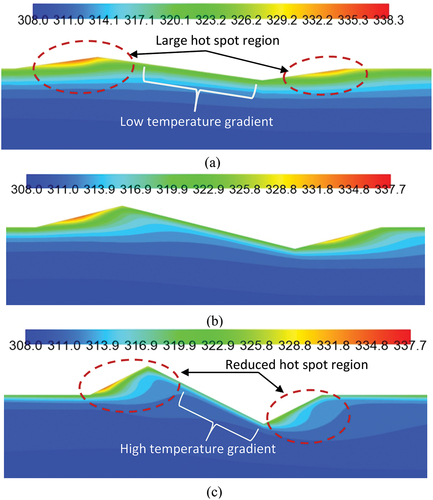
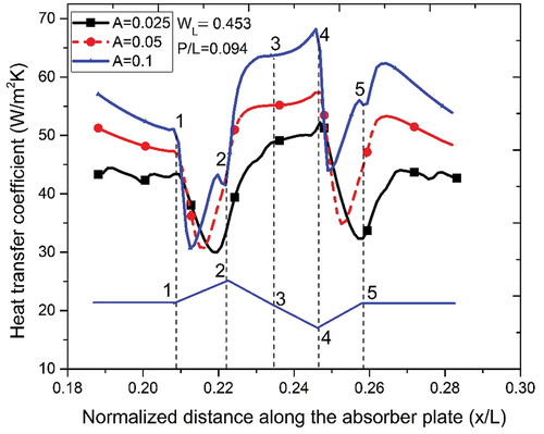
A further insight into the heat transfer mechanism around the corrugation can be obtained by plotting the variation of heat transfer coefficient along the corrugation surface, as shown in ). The variation of heat transfer coefficient clearly indicates the presence of considerable flow disturbances on both the sides of corrugation. It is seen that the heat transfer is poor along the corrugation surface A–B due to flow entrapment within the crest region. The extent of flow entrapment or the presence of stagnant flow within the crest region depends on the amplitude as well as the wavelength of corrugation. The stagnant flow is characterized by low heat transfer zones, as shown in ), where a closer look at the temperature distribution (refer )) in the airflow along the surface A–B reveals the presence of relatively higher temperature regions, also referred to as hotspots. The size and temperature of these hotspots depend largely on the amplitude and wavelength of corrugation. It is to be noted that the hotspots are predominant around the corner region at “B”, which exhibits the lowest heat transfer, as shown in ). Interestingly, the heat transfer begins to gradually rise along the surface B–C owing to its contact with the incoming colder airstream. It is to be noted that part of the incoming airstream deflected into the crest region along the surface B–C gets heated up as it moves upwards towards the stagnant region at “B”. As a result, the heat transfer is relatively higher on the surface close to region “C” as compared to region “B”. The surface C–D exhibits a further rise in heat transfer owing to the scouring effect caused by the incoming colder airstream, as seen in ). The colder airstream that comes in closer contact with the heated absorber surface causes thermal boundary layer thinning by increasing the temperature gradient, thereby augmenting the heat transfer. The surface D–E is in contact with the recirculation flow that circulates in the anti-clockwise direction. The flow pattern of recirculation flow is such that it first sweeps through the absorber surface, thereby allowing the colder airstream to come in contact with the heated absorber plate right in front of corrugation. As a result, the air temperature rises, which subsequently moves ahead and comes in contact with the surface D–E, as seen in ). As a result, the temperature gradient between the corrugation surface D–E and the hot airstream reduces, which lowers the heat transfer as indicated by relatively lower heat transfer coefficient in ).
Figure 6. Variation of (a) heat transfer coefficient along the corrugation surface for different pitch conditions and (b) temperature distribution in the airflow over the corrugation surface.
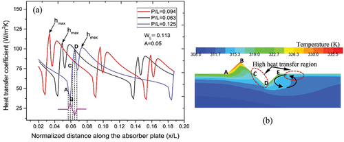
This airstream, as it moves further ahead, subsequently comes in contact with a relatively colder main flow, which augments flow mixing as well as heat energy transfer between the two streams. On the contrary, the recirculation flow in the crest region, on the upstream side of the corrugation, comes in contact with high-temperature airstream that is in close proximity to the heated absorber surface which limits the heat energy exchanger between the two fluid streams. As a result, the hotspots formed in the crest region are at a higher temperature than the hotspots formed in the trough region, as evident in ). Further, the heat transfer coefficient is found to reduce gradually on the downstream side of the corrugation owing to flow reattachment of separated flow with the absorber surface and subsequent redevelopment of the boundary layer region, which limits the heat transfer process between the airstream and absorber surface, as seen in ).
also shows the comparison of the Nusselt number for different non-dimensional pitches of 0.063, 0.094 and 0.125 for a given non-dimensional wavelength and amplitude of 0.113 and 0.05, respectively. It can be seen that a larger pitch distance reduces the heat transfer owing to the reduced number of corrugations on the absorber plate, which weakens the influence of corrugations on heat transfer. This aspect is very clear in ), which depicts an increased number of instances of peak heat transfer coefficient induced by corrugations for lower pitch values. An interesting pattern is observed in the location of peak heat transfer coefficient “hmax” for different pitch values, as seen in ), where the peak values are found to shift gradually from the recirculation zone in the downstream region of corrugation to its crest region. This is due to the fact that at larger pitch values, the flow constriction is much lower and the flow velocity augmentation in the duct is relatively smaller. As a result, the flow impingement effect is induced by a relatively lower velocity airstream. However, as the pitch reduces, the flow constriction effect increases, which causes the flow to accelerate through the duct. As a result, the flow impingement effect is caused by a relatively faster airstream that augments heat transfer to a greater extent in comparison to other pitch conditions. The Nusselt number improvement is found to be in the range of 1.45–1.75 depending on the corrugation pitch for a given non-dimensional wavelength and amplitude of 0.113 and 0.05, respectively.
figure also depicts the variation of friction factor enhancement for different non-dimensional pitches of 0.063, 0.094 and 0.125 used in the analysis. The friction factor for smooth duct is determined using the below equation. The friction factor for smooth duct is determined from the modified Blasius equation (Bhagoria et al., Citation2002) given by
The friction factor for circular tube in the presence of vortex generator is determined using the below equation:
Lower pitch values exhibit a higher friction factor penalty owing to the presence of a larger number of corrugations on the absorber plate, which increases the flow obstruction caused by the corrugation crest region that protrudes into the main flow, causing pressure loss across the duct. As the pitch distance increases, the number of corrugations reduces, thereby reducing the flow constriction and pressure drop. The friction factor enhancement is found to be in the range of 1.54–1.83 depending on the corrugation pitch non-dimensional wavelength and amplitude of 0.113 and 0.05, respectively.
3.2. Influence of corrugation wavelength
The influence of non-dimensional corrugation wavelength for a fixed amplitude of A = 0.1 on Nusselt number and friction factor is depicted in for different flow Reynolds number conditions. The Nusselt number is found to increase as the wavelength increases from 0.113 to 0.453 for all flow rates used in the analysis. A comparison of flow patterns at different wavelength values, as shown in , reveals the presence of different levels of flow disturbance around the corrugations, which indicates that the wavelength variation has a considerable influence on the flow structure.
Figure 7. Comparison of the Nusselt number and friction factor for different non-dimensional wavelengths and A = 0.1.
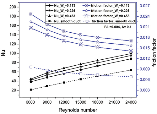
Figure 8. Comparison of the flow pattern and turbulence intensity (in %) for (a) WL = 0.113, (b) WL = 0.226 and (c) WL = 0.453 for A = 0.1.
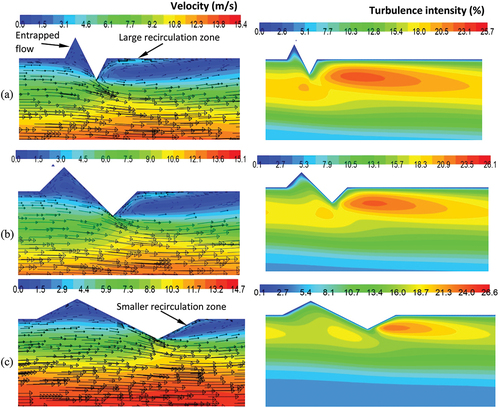
For WL = 0.113, the trough and crest regions are found to be narrow and are characterized by the presence of constricted recirculation flow in the narrow crest region on the upstream side, as shown by the velocity vector plots in ). In addition, the flow impingement region is also found to be relatively smaller. As a consequence, the part of the deflected flow from the flow impingement will not reach the entire crest region and there will always be some flow entrapment at the top corner region of the crest, as seen in ), which is detrimental for heat transfer. However, the recirculation region in the downstream side is found to be relatively large and is found to interact well with the separated flow, as seen in ). It is also noted that the corrugation surface on which the flow impingement takes place is relatively more normal to the incoming flow, which creates greater flow disturbance as is evidenced by elevated turbulence intensity levels for larger flow regions around the corrugation in ) for WL = 0.113. As the wavelength increases from 0.113 to 0.226, notable changes are observed in the flow pattern, as shown in the velocity vector plots in ). The recirculation regions on the downstream sides of corrugation are reduced in size and the flow impingement region, which creates a scouring effect on the corrugation, is also found to be relatively larger, which augments heat transfer. It can be seen that the flow turbulence levels as revealed by the turbulence intensity plots in ) and ) are comparable for both WL = 0.113 and WL = 0.226. As the wavelength increases further to 0.453, the crest and trough region further expands, which in turn overcomes the flow constriction in the recirculation zone, as seen in the velocity vector plot in ).
Also, the size of the recirculation region on the downstream reduces as the flow coming off the trough surface upon flow impingement will be guided more into the downstream region as is evident in the velocity vector plot in ). However, the flow turbulence levels fall slightly as indicated by slightly lower turbulence intensity in ) due to reduced flow disturbance in the airstream around the corrugations as a result of more streamlined alignment of the corrugation trough surface for the incoming flow. Thus, the overall effect of wavelength variation on the flow pattern is that the recirculation zones on the downstream side shrinks with increasing wavelength, while the constriction enforced on the recirculation flow in the narrow crest region is relaxed. A further insight into heat transfer performance effected by the flow pattern variation for different wavelengths can be obtained by plotting the variation of heat transfer coefficient along the corrugation surface, as shown in . The corresponding locations of corrugation surface are also highlighted using letters A, B, C, D and E in the figure for a particular case of WL = 0.453. The heat transfer coefficient is clearly seen to be greater for WL = 0.453 as compared to other configurations.
Figure 9. Variation of (a) heat transfer coefficient along the corrugation surface for different pitch conditions.
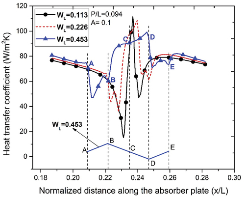
The heat transfer on the surface A–B is seen to be lower due to the presence of hotspots in the recirculation region. However, it is to be noted that the drop in heat transfer is relatively lower in this region due to the reduced size and lower temperature of hotspots, as seen in ), in comparison to other wavelength configurations. For the surface B–C, the heat transfer coefficient rises due to flow impingement of incoming colder airstream, which increases heat transfer significantly and as seen in . For the surface D–E, the trough surface guides the colder main flow towards the recirculation region, which interacts with the recirculation flow and carries away the heat energy, thereby reducing the temperature in this region. It is noted that the heat transfer is still limited on this surface and therefore the heat transfer coefficient shows a downward trend. In comparison to WL = 0.453, for WL = 0.113, the crest region is narrow and has an already entrapped flow in its corner region, which gets heated up due to the lack of interaction with the main flow, thereby forming a larger hotspot region that is at an elevated temperature, as seen in ). Therefore, the heat transfer coefficient is much lower in the crest region for WL = 0.113 and shows a larger drop in heat transfer as clearly seen by the sharp decline in heat transfer coefficient in the crest region in . The hotspots are present for the most part of the crest region at lower wavelengths and are seen to gradually reduce as the wavelength increases, as seen in ) and ). The peak heat transfer coefficient for WL = 0.453 is seen to exist for a relatively larger distance along the flow impingement region due to the altered geometry of corrugation that provides a relatively longer corrugation surface to the incoming airstream.
Figure 10. Comparison of temperature distribution for (a) WL = 0.113, (b) WL = 0.226 and (c) WL = 0.453 at A = 0.1.
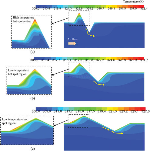
Thus, for a given amplitude of A = 0.1, the configuration having WL = 0.453 produces greater heat transfer owing to the reduced hot spot regions and improved flow mixing between the main flow and the near wall flows effected by the corrugation geometry. It is interesting to note that the surface area improvement for heat transfer due to corrugation is about 15.31% for WL = 0.113, 10.31% for WL = 0.226 and 5.93% for WL = 0.453 in comparison to smooth duct for A = 0.1. Clearly, smaller wavelengths provide higher heat transfer area enhancement.
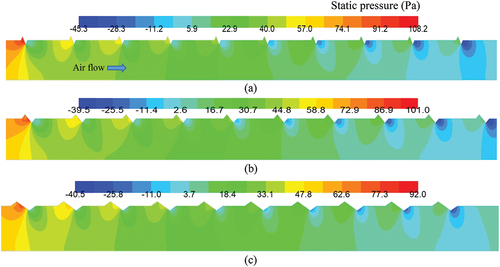
also shows the effect of wavelength on friction factor penalty that is incurred to achieve the heat transfer improvement for different wavelengths at A = 0.1. The friction factor is found to be higher for lower wavelengths due to the increased pressure drop in the flow due to increased flow obstruction caused by the corrugation trough surface to the incoming flow, as seen in ). For lower wavelengths, the trough surface is more normal to the incoming flow and causes increased flow obstruction causing local pressure rise. In addition, the downstream region is found to have relatively lower pressure due to the formation of a larger recirculation zone at lower wavelengths. As the wavelength increases, the trough surface of the corrugation offers relatively less obstruction to the incoming flow and causes a lower pressure drop, as evident in ). Thus, the variation of corrugation wavelength is found to have a significant influence on friction factor characteristics in solar air heater systems.
Figure 11. Comparison of static pressure distribution (Pa) in the airflow through the duct for (a) WL = 0.113, (b) WL = 0.226 and (c) WL = 0.453 at A = 0.1.
3.3. Influence of corrugation amplitude
The influence of non-dimensional corrugation amplitude (A = 0.025, 0.05 and 0.1) for a fixed wavelength of WL = 0.453 on the Nusselt number and friction factor is depicted in for different flow Reynolds number conditions. The Nusselt number is found to be considerably higher than the smooth duct for all configurations used in the analysis. The Nusselt number is also seen to be considerably influenced by the variation of the amplitude of corrugation. It is observed that higher amplitude exhibits a higher increase in the Nusselt number owing tothe increased flow disturbance effects. An insight into the flow patterns in ) reveals that for A = 0.025, the corrugation crest and trough regions do not interfere much with the incoming flow, thereby limiting the disturbances necessary for enhanced flow turbulence to achieve improved heat transfer.
Figure 12. Comparison of the Nusselt number and friction factor for different non-dimensional amplitudes and WL = 0.453.
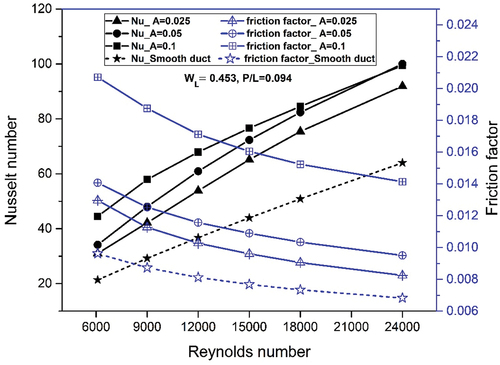
Figure 13. Comparison of the flow pattern and turbulence intensity (in %) for (a) A = 0.025, (b) A = 0.05 and (c) A = 0.1 at WL = 0.453.
The corrugation surface is found to be more streamlined with flow, and the recirculation zones on both sides of corrugation are much smaller in size. As a result, the flow disturbances are found to be at a lower level and the incoming airstream moves over the corrugation with less flow fluctuations, which results in lower turbulence levels around the corrugations as evidenced by the turbulence intensity distribution plot in ) for A = 0.025. It is clearly seen that the influence of flow turbulence is limited to a relatively smaller region of flow close to the corrugation surface. This limits the extent of heat energy exchange within the fluid stream as well as between the absorber plate and the airstream. A further insight into the temperature distribution plots reveals the presence of hotspots that are larger in size as well as higher in temperature, as shown in ), for A = 0.025. Since, for lower amplitude values, the trough region of corrugation does not interfere much with the main flow, which is relatively colder as compared to that which is in close contact with the absorber surface, the separated flow that interacts with the recirculation zone in the downstream side is relatively hot, which limits the heat energy exchange between the two airstreams.
Figure 14. Comparison of temperature distribution for (a) A = 0.025, (b) A = 0.05 and (c) A = 0.1 at WL = 0.453.
Since the flow turbulence is at a lower level around the corrugation, the heat energy exchange is further limited and therefore a relatively high temperature region (large green band in )) is seen close to the corrugation surface. As a result, a high-temperature hotspot is formed in the downstream recirculation region, as seen in ). Further, as the airstream moves ahead, the recirculating flow in the upstream side of the corrugation interacts with this relatively high temperature airstream, leading to the formation of another high temperature hotspot, as seen in ). It is noted that the upstream hot spot is relatively larger in size as it interacts with airstream that is in close proximity to the absorber surface and has much higher temperature. These hot spots exhibit poor heat transfer on either side of the corrugation. As the amplitude increases from A = 0.025 to A = 0.1, the geometry of the corrugation changes in such a way that the trough region gradually protrudes more into the main flow region, while the crest region moves away from the main flow region, as seen in ) and ). The crest region of corrugation now starts to interfere more and more with the incoming colder main flow, which causes an increased scouring effect on the corrugation surface, thereby enhancing the heat transfer. In addition, the flow turbulence levels also increase as is evidenced by the presence of large regions of higher turbulence intensity in ) and ) for A = 0.05 and A = 0.1, respectively. The recirculation zones formed on both sides of the corrugation are seen to grow in size with increasing amplitude. Due to the increased interference of the trough region of corrugation with the main flow, the recirculation region in the downstream side now interacts with the incoming colder main flow, which increases heat energy transfer and eventually reduces the air temperature within the recirculation zone on the downstream side as is clearly seen by the reduced size of the hotspot in ) and ) for A = 0.05 and A = 0.1 respectively.
These aspects can be further corroborated by plotting the variation of heat transfer coefficient on the corrugation surface, as shown in . It is clearly seen that the heat transfer coefficient is higher for A = 0.1 on the entire corrugation surface designated as 1–2–3–4–5, and similar pattern is observed for all amplitudes used in the analysis. The heat transfer is lower on the surface 1–2 due to the presence of a hotspot, while peak heat transfer takes place on the surface 2–3–4 where the flow impingement effect from the incoming colder main flow increases the temperature gradient for heat transfer, as shown in ).
Figure 15. Variation of the heat transfer coefficient along the corrugation surface for different non-dimensional amplitudes at WL = 0.453.
The heat transfer peaks again in the downstream recirculation region after location “5” for A = 0.1, as seen in , due to high turbulence levels and reduced hotspot region in the recirculation flow. The highest increase in the Nusselt number is found to be about 2.082 times that of the smooth duct for the configuration having an amplitude of 0.1 at Re = 6000. The improvement in the Nusselt number for various configurations used in the analysis is listed in for different flow Reynolds numbers. From the table, it is observed that for a given wavelength, a larger amplitude of corrugation is required to achieve increased heat transfer. It is also noted that the surface area improvement for heat transfer due to corrugation is 0.31% for A = 0.025, 1.56% for A = 0.05 and 5.93% for A = 0.1 compared to the smooth duct for WL = 0.453. Clearly, a larger amplitude provides higher heat transfer area enhancement and is significantly lower than the corresponding area enhancement with wavelength variation.
Table 3. Nusselt number enhancement values of various corrugation configurations
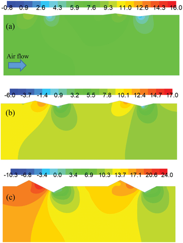
However, since the corrugations cause flow disturbance that is associated with pressure energy loss, the friction factor penalty of using the corrugation also becomes an important consideration in determining the efficacy of corrugations for effective heat transfer enhancement. From , it is seen that the friction factor is considerably higher for higher amplitudes owing to the increased flow interference by the trough region of corrugation with the main flow. shows that the pressure variations are significantly higher for higher amplitude values. A rise in static pressure is observed on the upstream surface of the trough region where the incoming flow impacts the corrugation. The subsequent flow separation results in the formation of a low-pressure region in the recirculation zone on the immediate downstream of corrugation, as seen in . For A = 0.025, since the corrugations are more streamlined to the flow, the flow interference is comparatively lower and hence the pressure drop is found to be at lower levels. Thus, it is clear that, although higher amplitudes enhance heat transfer significantly, they are also associated with increased friction factor penalty. shows the friction factor enhancement obtained for various corrugation configurations used in the analysis. It is clear from the table that, for a given wavelength, higher amplitudes exhibit greater friction factor enhancement. The highest increase in friction factor is about 2.568 times that of the smooth duct at Re = 6000 for the configuration of WL = 0.113 and A = 0.1.
Table 4. Friction factor enhancement values of various corrugation configurations
Figure 16. Static pressure distribution for (a) A = 0.025, (b) A = 0.05 and (c) A = 0.1 at WL = 0.453.
3.4. Thermal enhancement factor
The thermal enhancement factor (TEF; Gill et al., Citation2021) indicates the effective gain in heat transfer after considering the corresponding friction factor penalty incurred in the process and is given by
) shows the variation of TEF for different corrugation pitches at WL = 0.113. It is seen that TEF improves as the pitch distance increases from 0.02 m to 0.03 m but shows a downward trend with a further increase in pitch distance of the corrugation. It was earlier seen in that the smaller pitch distance provides higher heat transfer but also exhibit higher friction factor penalty. The rise in Nusselt number and friction factor for P/L = 0.063 is in the range of 1.54–1.73 and 1.73–1.83 while it is in the range of 1.48–1.66 and 1.59–1.65 for P/L = 0.094 respectively. Therefore, although the average increase in Nusselt number for P = 0.03 m is lower than P/L = 0.094 by about 2.71%, the corresponding friction factor penalty is about 9.55% lower. As a result, the non-dimensional pitch of 0.094 produces marginally higher TEF than P/L = 0.063. Although this is insignificant in terms of the relative difference in overall thermal performance, the usea of lower non-dimensional pitch of 0.094 can be beneficial instead of 0.063 as fewer corrugations are required to be used on the absorber plate for the same effective thermal gain.
Figure 17. Comparison of TEF for (a) different non-dimensional pitches at WL = 0.113, (b) different wavelengths at A = 0.1 and (c) different amplitudes at WL = 0.453 for different flow Reynolds numbers.
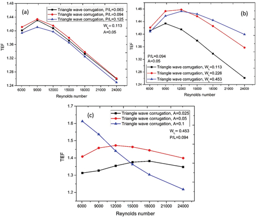
) shows the variation of TEF for different corrugation wavelengths at A = 0.1 and 0.094 for different flow rates of air. It is clearly seen that the variation of corrugation wavelength significantly influences the overall thermal performance of solar air heaters. For a given amplitude, a longer wavelength is found to provide greater overall thermal gain. The Nusselt number enhancement for WL = 0.453, WL = 0.226 and WL = 0.113 is in the range of 1.55–2.08, 1.49–1.96 and 1.37–1.8, respectively. The friction factor enhancement for WL = 0.453, WL = 0.226 and WL = 0.113 is in the range of 2.07–2.15, 2.27–2.34 and 2.44–2.56, respectively. Clearly, for WL = 0.453, the Nusselt number enhancement is the highest, while its friction factor enhancement is the lowest. The average Nusselt number enhancement for WL = 0.453 is about 6.5% higher than that for WL = 0.226 and about 14.84% higher than that for WL = 0.113. At the same time, the friction factor penalty for WL = 0.453 is about 9.01% lower than that for WL = 0.226 and about 17.88% lower than that for WL = 0.113. Therefore, the TEF for WL = 0.453 is found to be considerably higher than those for other wavelengths used in the analysis. It was earlier seen that the use of higher corrugation wavelength overcomes the hotspots to a considerable extent and also offers lower flow obstruction due to the relatively more streamlined alignment of its trough region to the incoming flow. Both these aspects are indicated by its higher TEF performance within the flow Reynolds number used in the analysis.
) shows the variation of TEF for different corrugation amplitudes at WL = 0.453 and P = 0.03 m for different flow rates of air. It is clearly seen that the corrugation amplitude has a significant influence on the the overall thermal performance of solar air heater system. For a given wavelength, the higher amplitude is found to provide greater TEF for the Reynolds number range of 6000–9000, beyond which the TEF for A = 0.1 decreases sharply. The Nusselt number increase for A = 0.025, A = 0.05 and A = 0.1 is found to be in the range of 1.43–1.45, 1.56–1.59 and 1.55–2.08, respectively, while the friction factor increase is in the range of 1.2–1.35, 1.39–1.46 and 2.07–2.15, respectively. The Nusselt number improvement for A = 0.1 is about 10.54% higher than that for A = 0.05 and 19.4% higher than that for A = 0.025. On the other hand, the friction factor enhancement is about 32.4% higher than that for A = 0.05 and about 39.9% higher than that for A = 0.025. Thus, it can be seen that although the improvement in heat transfer is significant for A = 0.1, the relative increase in friction factor overwhelms the heat transfer gain over the configurations having A = 0.025 and A = 0.05. Therefore, the configuration having A = 0.1 exhibits significantly higher TEF at a lower Reynolds number range of 6000–9000 within which the friction factor enhancement is in the range of 2.15–2.14, which is comparable to the corresponding Nusselt number enhancement in the range of 2.08–1.98. Thus, the corrugation amplitude of A = 0.1 is particularly more beneficial for lower flow rate conditions, while the amplitude of A = 0.05 and A = 0.025 can be used for all the flow rates used in the analysis.
It should be noted that although A = 0.1 performs the best at lower flow rate conditions, it exhibits TEF greater than 1 for all the flow rates used in the analysis and has a TEF range of 1.218–1.612. It also exhibits the highest TEF of about 1.612 at Re = 6000 among all the configurations considered in the present study. Thus, it can be inference that for a fixed wavelength of WL = 0.453, the configuration having A = 0.1 can be used particularly for lower flow rate requirements, while A = 0.05 provides a relatively steady TEF performance over a wide range of flow rates with a maximum TEF of 1.473 at Re = 12,000. The TEF performance of various configurations used in the study is given in .
Table 5. TEF values of various corrugation configurations
3.5. Correlation for the Nusselt number and friction factor
The analysis reveals that the Nusselt number and friction factor strongly depends on the flow Reynolds number, amplitude and wavelength of corrugation for a given non-dimensional pitch of 0.094. Thus, the following functional relationship can be considered for the Nusselt number and friction factor:
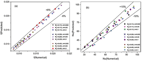
The correlations are developed using the curve fitting process, and the same procedure as outlined in Bhagoria et al. (Citation2002) is used in developing the correlations. The developed correlations are applicable for a non-dimensional pitch of 0.094, an amplitude of A = 0.025–0.1, WL = 0.113–0.452 and Re = 6000–24000. These correlations are helpful in determining the optimum parameters of amplitude and wavelength for a given flow Reynolds number condition relevant to a given application in order to achieve the desired level of heat transfer with minimal friction factor penalty using available optimization techniques. The results predicted by the correlations are found to agree well with the numerical results within ±10% for the Nusselt number and ±8% for friction factor, as shown in .
Figure 18. Comparison of (a) predicted friction factor and (b) predicted Nusselt number based on correlations with those of numerical results.
4. Comparison with previous works
A detailed comparison of the TEF performance of the present study with that of different turbulence promoters reported in the past studies is shown in .
The comparison reveals that the TEF is generally higher for inclined ribs and vortex generator designs owing to the generation of secondary vortices that flow down the airstream than being stagnant like in the case of transverse ribs. This leads to the increased flow mixing between the cold and hot airstreams near the heated absorber plate, which improves the TEF performance. The same is the case with vortex generators (Dong et al., Citation2021; Maithani et al., Citation2020; Promvonge et al., Citation2021; Skullong et al., Citation2018; Zhao et al., Citation2021), which generate strong longitudinal vortices that are spread over a relatively larger region on the absorber surface, which provides significant TEF performance. From this perspective, the triangular wave corrugation used in the present study is found to perform well when compared with the transverse rib designs such as hybrid semi-circular and rectangular ribs (Alfarawi and Bodalal, Citation2017), hybrid semi-circular and triangular ribs (Sahu et al., Citation2019) and U-shaped ribs (Yadav et al., Citation2021). This clearly indicates that a further investigation of discrete triangular wave corrugations with inclination to the incoming flow in the form of V-shape or W-shape could be promising to further enhance the TEF performance.
5. Conclusions
The study consists of two-dimensional CFD analysis to evaluate the efficacy of discrete triangle wave corrugations on the absorber plate of a solar air heater system for the Reynolds number range of 6000–24000. A parametric CFD analysis is carried out by varying the pitch, wavelength and amplitude of corrugation. The following major conclusions can be drawn from the analysis:
The lower the non-dimensional pitch, the higher the enhancement in the Nusselt number and friction factor.
The highest increase in the Nusselt number is found to be about 2.082 times that of the smooth duct for the configuration having an amplitude of A = 0.1 at Re = 6000.
The maximum rise in friction factor is about 2.568 times that of the smooth duct at Re = 6000 for the configuration of WL = 0.113 and A = 0.1.
The configuration of A = 0.1 exhibits the highest TEF of about 1.612 at Re = 6000 among all the configurations considered in the present study.
For a fixed wavelength of WL = 0.453, the configuration having A = 0.05 provides a relatively steady TEF performance over a wide range of flow rates with a maximum TEF of 1.473 at Re = 12,000.
6. Nomenclature
Acknowledgements
The authors express their gratitude and acknowledge the computational facilities provided by the Department of Mechanical and Industrial Engineering, Manipal Institute of Technology, MAHE, Manipal in carrying out this research work. This research did not receive any specific grant from any funding agencies.
Disclosure statement
No potential conflict of interest was reported by the author(s).
Additional information
Funding
Notes on contributors
Manjunath M S
Manjunath M S is an academician with experience of over 13 years in teaching undergraduate and postgraduate students of mechanical engineering and has a doctoral degree in thermal engineering. The key research activities carried out by the author and his group include experimental and computational investigations of heat transfer enhancement in solar air heaters, heat exchangers and solar distillation systems. The present research findings are very useful in the application of solar air heaters that provide enhanced heat transfer with limited flow energy loss by making use of specially designed triangular wavy corrugations on the absorber surface. Poor heat transfer in solar air heater systems leads to a larger exposure area requirement for solar heat absorption, which in turn demands greater floor space and eventually adds to the device cost that needs to be resolved. The proposed corrugations have been shown to significantly enhance heat transfer capability of solar air heaters and address the above issues well.
References
- Aboghrara, A. M., Baharudin, B. T. H. T., Alghoul, M. A., Adam, N. M., Hairuddin, A. A., & Hasan, H. A. (2017). Performance analysis of solar air heater with jet impingement on corrugated absorber plate. Case Studies in Thermal Engineering , 10(May), 111–34. https://doi.org/10.1016/j.csite.2017.04.002
- Alfarawi, S. A. A.-M., & Bodalal, A. (2017, August). Experimental investigations of heat transfer enhancement from rectangular duct roughened by hybrid ribs. International Journal of Thermal Sciences, 118, 123–138. https://doi.org/10.1016/j.ijthermalsci.2017.04.017
- Azad, R., Bhuvad, S., & Lanjewar, A. (2021, September). Study of solar air heater with discrete arc ribs geometry: Experimental and numerical approach. International Journal of Thermal Sciences, 167, 107013. https://doi.org/10.1016/j.ijthermalsci.2021.107013
- Barik, A. K., Mohanty, A., Senapati, J. R., & Awad, M. M. (2021, February). Constructal design of different ribs for thermo-fluid performance enhancement of a solar air heater (SAH). International Journal of Thermal Sciences, 160, 106655. https://doi.org/10.1016/j.ijthermalsci.2020.106655
- Bezbaruah, P. J., Das, R. S., & Sarkar, B. K. (2021, August). Experimentally validated 3D simulation and performance optimization of a solar air duct with modified conical vortex generators. Solar Energy, 224, 1040–1062. https://doi.org/10.1016/j.solener.2021.06.052
- Bhagoria, J. L., Saini, J. S., & Solanki, S. C. (2002, March). Heat transfer coefficient and friction factor correlations for rectangular solar air heater duct having transverse wedge shaped rib roughness on the absorber plate. Renewable Energy, 25(3), 341–369. https://doi.org/10.1016/S0960-1481(01)00057-X
- Bhuvad, S. S., Azad, R., & Lanjewar, A. (2021, December). Thermal performance analysis of apex-up discrete arc ribs solar air heater-an experimental study. Renewable Energy 185 . https://doi.org/10.1016/j.renene.2021.12.037
- Chamoli, S., Lu, R., Xie, J., & Yu, P. (2018, May). Numerical study on flow structure and heat transfer in a circular tube integrated with novel anchor shaped inserts. Applied Thermal Engineering, 135, 304–324. https://doi.org/10.1016/j.applthermaleng.2018.02.052
- Chamoli, S., Zhuang, X., Kumar Pant, P., & Yu, P. (2021, July). Heat transfer in a turbulent flow tube integrated with tori as vortex generator inserts. Applied Thermal Engineering, 194, 117062. https://doi.org/10.1016/j.applthermaleng.2021.117062
- Dezan, D. J., Rocha, A. D., Salviano, L. O., & Ferreira, W. G. (2020, September). Thermo-hydraulic optimization of a solar air heater duct with non-periodic rows of rectangular winglet pairs. Sol. Energy, 207, 1172–1190. https://doi.org/10.1016/j.solener.2020.06.112
- Dong, Z., Liu, P., Xiao, H., Liu, Z., & Liu, W. (2021). A study on heat transfer enhancement for solar air heaters with ripple surface. Renewable Energy, 172, 477–487. https://doi.org/10.1016/j.renene.2021.03.042
- Ebrahim Momin, A.-M., Saini, J. S., & Solanki, S. C. (2002, July). Heat transfer and friction in solar air heater duct with V-shaped rib roughness on absorber plate. International Journal of Heat and Mass Transfer, 45(16), 3383–3396. https://doi.org/10.1016/S0017-9310(02)00046-7
- El Ferouali, H., Doubabi, S., Kouhila, M., & Abdenouri, N. (2018). Exergy for A Better Environment and Improved Sustainability 1. In Green Energy and Technology (pp. 303–317). Springer, Cham. https://doi.org/10.1007/978-3-319-62572-0_21
- El-Sebaii, A. A., Aboul-Enein, S., Ramadan, M. R. I., Shalaby, S. M., & Moharram, B. M. (2011). Investigation of thermal performance of-double pass-flat and v-corrugated plate solar air heaters. Energy, 36(2), 1076–1086. https://doi.org/10.1016/j.energy.2010.11.042
- Farhan, A. A., Issam, A., Ali, M., & Ahmed, H. E. (2021). Energetic and exergetic efficiency analysis of a v-corrugated solar air heater integrated with twisted tape inserts. Renewable Energy, 169, 1373–1385. https://doi.org/10.1016/j.renene.2021.01.109
- Gill, R. S., Hans, V. S., & Singh, R. P. (2021, June). Optimization of artificial roughness parameters in a solar air heater duct roughened with hybrid ribs. Applied Thermal Engineering, 191, 116871. https://doi.org/10.1016/j.applthermaleng.2021.116871
- Gupta, D., Solanki, S. C., & Saini, J. S. (1993). Heat and fluid flow in rectangular solar air heater ducts having transverse rib roughness on absorber plates. Solar Energy, 51(1), 31–37. https://doi.org/10.1016/0038-092X(93)90039-Q
- Ho, C. D., Chang, H., Hsiao, C. F., & Lin, Y. C. (2021). Optimizing thermal efficiencies of double-pass cross-corrugated solar air heaters on various configurations with external recycling. Energies, 14(13), 4019. https://doi.org/10.3390/en14134019
- Ho, C. D., Hsiao, C. F., Chang, H., Tien, Y. E., & Hong, Z. S. (2017). Efficiency of recycling double-pass V-corrugated solar air collectors. Energies, 10(7), 1–15. https://doi.org/10.3390/en10070875
- Ho, C. D., Tien, Y. E., & Chang, H. (2016). Performance improvement of a double-pass V-corrugated solar air heater under recycling operation. International Journal of Green Energy, 13(15), 1547–1555. https://doi.org/10.1080/15435075.2016.1206004
- Jaurker, A. R., Saini, J. S., & Gandhi, B. K. (2006, August). Heat transfer and friction characteristics of rectangular solar air heater duct using rib-grooved artificial roughness. Solar Energy, 80(8), 895–907. https://doi.org/10.1016/j.solener.2005.08.006
- Jin, D., Quan, S., Zuo, J., & Xu, S. (2019, April). Numerical investigation of heat transfer enhancement in a solar air heater roughened by multiple V-shaped ribs. Renewable Energy, 134, 78–88. https://doi.org/10.1016/j.renene.2018.11.016
- Karim, M. A., & Hawlader, M. N. A. (2006). Performance evaluation of a v-groove solar air collector for drying applications. Appl. Therm. Eng, 26(1), 121–130. https://doi.org/10.1016/j.applthermaleng.2005.03.017
- Kumar, A., & Layek, A. (2018, November). Thermo-hydraulic performance of solar air heater having twisted rib over the absorber plate. International Journal of Thermal Sciences, 133, 181–195. https://doi.org/10.1016/j.ijthermalsci.2018.07.026
- Kumar, S., & Saini, R. P. (2009, May). CFD based performance analysis of a solar air heater duct provided with artificial roughness. Renewable Energy, 34(5), 1285–1291. https://doi.org/10.1016/j.renene.2008.09.015
- Lin, W., Gao, W., & Liu, T. (2006). A parametric study on the thermal performance of cross-corrugated solar air collectors. Applied Thermal Engineering, 26(10), 1043–1053. https://doi.org/10.1016/j.applthermaleng.2005.10.005
- Mahanand, Y., & Senapati, J. R. (2021). Thermo-hydraulic performance analysis of a solar air heater (SAH) with quarter-circular ribs on the absorber plate: A comparative study. International Journal of Thermal Sciences, 161, 106747. https://doi.org/10.1016/j.ijthermalsci.2020.106747
- Maithani, R., Kumar, A., Gholamali Zadeh, P., Safaei, M. R., & Gholamalizadeh, E. (2020, January). Empirical correlations development for heat transfer and friction factor of a solar rectangular air passage with spherical-shaped turbulence promoters. Journal of Thermal Analysis and Calorimetry, 139(2), 1195–1212. https://doi.org/10.1007/s10973-019-08551-8
- Manjunath, M. S., Karanth, K. V., & Sharma, N. Y. (2017, February). Numerical analysis of the influence of spherical turbulence generators on heat transfer enhancement of flat plate solar air heater. Energy, 121, 616–630. https://doi.org/10.1016/j.energy.2017.01.032
- Manjunath, M. S., Karanth, K. V., & Sharma, N. Y. (2018). Numerical investigation on heat transfer enhancement of solar air heater using sinusoidal corrugations on absorber plate. International Journal of Mechanical Sciences, 138-139(February), 219–228. https://doi.org/10.1016/j.ijmecsci.2018.01.037
- Manjunath, M. S., Venkatesh, R., & Madhwesh, N. (2019). Thermal performance enhancement of flat plate solar air heater using transverse U-shaped turbulator - A numerical study. Journal of Mechanical Engineering Science, 13(3), 5562–5587. https://doi.org/10.15282/jmes.13.3.2019.22.0448
- Patel, Y. M., Jain, S. V., & Lakhera, V. J. (2021, September). Thermo-hydraulic performance analysis of a solar air heater roughened with discrete reverse NACA profile ribs. International Journal of Thermal Sciences, 167, 107026. International Journal of Thermal SciencesInternational Journal of Thermal Scienceshttps://doi.org/10.1016/j.ijthermalsci.2021.107026
- Poongavanam, G. K., Panchabikesan, K., Leo, A. J. D., & Ramalingam, V. (2018). Experimental investigation on heat transfer augmentation of solar air heater using shot blasted V-corrugated absorber plate. Renewable Energy, 127, 213–229. https://doi.org/10.1016/j.renene.2018.04.056
- Prakash, C., & Saini, R. P. (2019, September). Heat transfer and friction in rectangular solar air heater duct having spherical and inclined rib protrusions as roughness on absorber plate. Experimental Heat Transfer, 32(5), 469–487. https://doi.org/10.1080/08916152.2018.1543367
- Promvonge, P., Promthaisong, P., & Skullong, S. (2021, August). Numerical heat transfer in a solar air heater duct with punched delta-winglet vortex generators. Case Studies in Thermal Engineering, 26, 101088. https://doi.org/10.1016/j.csite.2021.101088
- Promvonge, P., & Skullong, S. (2021). Thermal characteristics in solar air duct with V-shaped flapped-baffles and chamfered-grooves. International Journal of Heat and Mass Transfer, 172, 121220. https://doi.org/10.1016/j.ijheatmasstransfer.2021.121220
- Sahu, M. K., Pandey, K. M., & Chatterjee, S. (2019, October). Thermo-hydraulic performance of rectangular channel roughened with combined semi-circular and triangular ribs. Heat and Mass Transfer, 55(10), 2889–2900. https://doi.org/10.1007/s00231-019-02630-0
- Saini, S. K., & Saini, R. P. (2008, December). Development of correlations for Nusselt number and friction factor for solar air heater with roughened duct having arc-shaped wire as artificial roughness. Solar Energy, 82(12), 1118–1130. https://doi.org/10.1016/j.solener.2008.05.010
- Sharma, N., Tariq, A., & Mishra, M. (2018, September). Detailed heat transfer and fluid flow investigation in a rectangular duct with truncated prismatic ribs. Experimental Thermal and Fluid Science, 96, 383–396. https://doi.org/10.1016/j.expthermflusci.2018.03.029
- Sharma, N., Tariq, A., & Mishra, M. (2019, January). Experimental investigation of heat transfer enhancement in rectangular duct with pentagonal ribs. Heat Transfer Engineering, 40(1–2), 147–165. https://doi.org/10.1080/01457632.2017.1421135
- Skullong, S., Promthaisong, P., Promvonge, P., Thianpong, C., & Pimsarn, M. (2018, August). Thermal performance in solar air heater with perforated-winglet-type vortex generator. Sol. Energy, 170, 1101–1117. https://doi.org/10.1016/j.solener.2018.05.093
- Yadav, A. S., Shrivastava, V., Kumar Chouksey, V., Sharma, A., Kumar Sharma, S., & Kumar Dwivedi, M. (2021). ”Enhanced solar thermal air heater: A numerical investigation”. Materials Today: Proceedings, 47(11), 2777–2783. https://doi.org/10.1016/j.matpr.2021.03.385
- Zhao, Z., Luo, L., Qiu, D., Wang, Z., & Sundén, B. (2021, June). On the solar air heater thermal enhancement and flow topology using differently shaped ribs combined with delta-winglet vortex generators. Energy, 224, 119944. https://doi.org/10.1016/j.energy.2021.119944