
ABSTRACT
In Europe, design for the durability of new reinforced concrete structures is currently based on a prescriptive approach. The design, execution (construction) and planned maintenance of a concrete structure have to lead to the intended level of safety and serviceability throughout its entire service life. This requires numeric models based on a sound scientific background of mechanistic understanding as the basis for design and management tools and for the further development of standards and regulations. Designers must understand the basic deterioration mechanisms and the potential types and rates of damage development. For example, different types of corrosion cause very different damage developments, some of which reduce structural safety. We propose that the next generation of service life models should either explicitly include the propagation period or implicitly include it by selecting an accepted probability of depassivation that reflects the type of corrosion and its structural implications.
1. Introduction
The design of reinforced concrete structures began towards the end of the 1800s, a time when this economical and versatile composite material was considered ‘eternal’, like natural stone. In the period 1950–1970, new highway systems were constructed all over Europe with many bridges, flyovers and tunnels. The term ‘durability’ had yet to appear in national design codes – with the dramatic consequence of a huge stock of structures that needed to be repaired or, even worse, re-repaired (Geiker et al., Citation2018; Polder et al., Citation2012). It was not until the 1980s that the term ‘durability’ started being considered just as important as ‘structural safety’ in the national design codes. Engineers, designers, contractors and owners all had to learn that environmental impacts, unlike most mechanical loads, are irreversible and become even more severe with time, as with the accumulation of chloride ions in concrete exposed to de-icing salts or sea water.
In Europe today, design for the durability of new reinforced concrete structures is based on a prescriptive approach. Environmental impacts (loads; named ‘environmental actions’ in the standard) are characterized in a set of exposure classes in EN 206 (CEN (European Committee for Standardization), Citation2013), and the resistance of the structure to these impacts is defined by a set of requirements, e.g., concrete strength class, w/c ratio, cement content (CEN (European Committee for Standardization), Citation2013), cover depth, crack width (CEN (European Committee for Standardization), Citation2004), needed to achieve the required service life without major repair work (for bridges, usually 100 years). If these limiting values are correctly applied in construction (CEN (European Committee for Standardization), Citation2009), it will be possible to eliminate most forms of deterioration, including corrosion, that are connected to incorrect design, material composition, or construction practice (Bertolini et al., Citation2013).
Another way to design for durability is the performance-based approach (DuraCrete, Citation2000; fib (Fédération International du Béton), Citation2006; ISO (International Organization for Standards), Citation2012). Here the owner sets the requirements (service life and required documentation) and the contractor proposes various solutions. This opens the way for more innovative solutions, but to make it possible to compare and validate the solutions, we need service life models as well as reliable performance test methods and acceptance criteria.
This paper addresses selected issues related to the European perspective on durability-based design for concrete structures with conventional reinforcement. Section 2 presents the European concrete standards and introduces the ‘exposure resistance class approach’. Section 3 presents the service life design approach developed, starting with the European DuraCrete project. Section 4 discusses the needs and possibilities for modelling improvements, while Section 5 addresses the need for mechanism-based models and for considering both durability and sustainability in the future design and operation of structures. Due to space limitations, maintenance is not covered here, but there is no doubt that proper maintenance practices (including inspection, assessment and repair) are central for ensuring sustainable and resilient infrastructure.
2. The european concrete standards
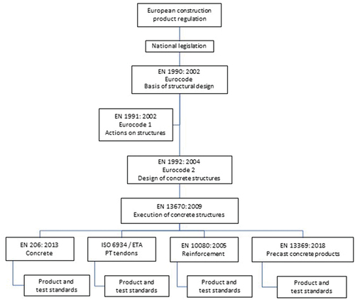
The hierarchy of European regulations and standards for reinforced concrete is shown in .
Figure 1. Hierarchy of European regulations and standards for reinforced concrete (main modules). (Helland, Citation2016).
2.1. Current design provisions in the european standards
In Europe, the durability of new reinforced concrete structures is currently based on prescriptive requirements (a.k.a. deemed-to-satisfy rules), where durability is assumed achieved by specifying limiting values for concrete composition according to EN 206 (CEN (European Committee for Standardization), Citation2013) and construction according to EN 13670 (CEN (European Committee for Standardization), Citation2009). The limiting values define the resistance of a concrete or a structural element to a set of environmental impacts, characterized by the exposure classes in the concrete standard EN 206 (CEN (European Committee for Standardization), Citation2013); see . Design standard EN 1992 (CEN (European Committee for Standardization), Citation2004) provides requirements for specific durability-related properties with regard to minimum cover and maximum crack widths.
Table 1. Exposure classes according to EN 206 (CEN (European Committee for Standardization), Citation2013). Table 1 is reproduced from NS-EN 206:2013+A1:2016+NA:2017 under licence to the first author from Standard Online AS July 2020. © all rights are reserved. Standard Online makes no guarantees or warranties as to the correctness of the reproduction. see www.standard.no.
To illustrate the design provisions given in EN 206 (CEN (European Committee for Standardization), Citation2013) and EN 1992 (CEN (European Committee for Standardization), Citation2004), the values recommended for exposure class XD, ‘Corrosion induced by chlorides other than from sea water’, are given in . It should be noted that the European standards are supplemented by national application documents, which results in variations in requirements between countries even where the environmental impacts are comparable. Helland (Citation2016) points out that a major explanation for the differences between the national requirements in Europe is the accepted probability of failure, which, for example for carbonation-induced depassivation, results in different design service lives for a given structure (see ) – or different cover thickness requirements for a given design service life.
Figure 2. Impact of the accepted probability of failure on the predicted service life assuming carbonation-induced depassivation: 2%: 50 years; 10%: 70 years; 30%: 93 years; 50%: 108 years. Norwegian standardization body applies 10%. (Helland, Citation2013).
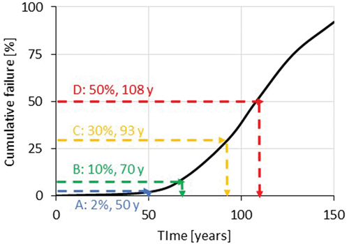
Table 2. Recommendations for the choice of limiting values according to EN 206 (CEN (European Committee for Standardization), Citation2013) for the concrete composition and properties for exposure class XD ‘corrosion induced by chlorides (Cl−) other than from sea water’. the limiting values for the maximum w/c ratio and the minimum cement content apply in all cases, and the concrete strength class may also be specified. Table 2 is reproduced from NS-EN 206:2013+A1:2016+NA:2017 under licence to the first author from Standard Online AS July 2020. © All rights are reserved. Standard Online makes no guarantees or warranties as to the correctness of the reproduction. see www.standard.no.
Table 3. Minimum values for concrete cover depth for conventional reinforcement according to EN 1992 (CEN (European Committee for Standardization), Citation2004) with regard to protection of steel from chloride-induced corrosion for structure class S4 (50 years’ design service life) and S6 (100 years’ design service life). these values should be increased by 10 mm to obtain the nominal cover depth. Table 3 is reproduced from NS-EN 1992–1-1:2004+A1:2014+NA:2018 under licence to the first author from Standard Online AS July 2020. © all rights are reserved. Standard Online makes no guarantees or warranties as to the correctness of the reproduction. see www.standard.no.
2.2. Exposure resistance classes for consistent durability design
To overcome the inconsistencies of the current European prescriptive approach, a new durability design concept, similar to the concept of strength classes, has been proposed (Von Greve-Dierfeld, Citation2015). Von Greve-Dierfeld and Gehlen (Von Greve-Dierfeld & Gehlen, Citation2016a, Citation2016b) present a system of exposure (materials) resistance classes for durability design and elaborate it for carbonation. Their starting point was a probabilistic form of the limit state equation for the carbonation of concrete, which compares the concrete cover with the carbonation depth at the end of the design service life. Applying a partial safety factor format results in design charts with values for the minimum concrete cover as a function of the material resistance and exposure class. Von Greve-Dierfeld and Gehlen (Citation2016c) provide further description and suggested statistical parameters and safety factor values.
The concept of Exposure Resistance Classes (ERCs) is currently being introduced in the next version of EN 1992–1. In the future, it is anticipated that performance verification might be undertaken based either on deemed-to-satisfy requirements as today or on performance testing and using the ERC concept.
We agree that the proposed ERC concept will provide increased transparency in the classification of concrete performance and facilitate a unification of concrete requirements at the European level. Moreover, the performance-based approach will support the introduction of new materials. However, the application of the ERC concept does require (i) that reliable performance test methods and criteria are available, and (ii) that knowledge about the impact of specific design conditions on long-term performance is available or that the design is based on conservative assumptions. This might limit the use of innovative solutions to some extent. A second issue is the anticipated limit state and the applied limit state function, which may be neither correct nor favourable to sustainable solutions.
3. Development of a conceptual approach to service life design
A conceptual approach to service life design was developed in Europe in the 1980s and early 1990s, mainly through the work of the Comité euro-international du béton (CEB)/Euro-International Committee for Concrete. Rostam (Citation1993) summarized the European service life design concept for new structures and illustrated it with design solutions employed in practice in the design of the Great Belt Link in Denmark. These design solutions reflect the so-called multi-stage protection strategy (Rostam, Citation1993).
3.1. The probabilistic performance-based durability design approach in the DuraCrete guidelines
The work of the CEB was continued in the EU-funded project DuraCrete – Probabilistic Performance Based Durability Design of Concrete Structures (Brite-EuRam BE95–1347), which provided guidelines for durability design and redesign (DuraCrete, Citation2000). In these guidelines, the models used to determine the time-to-depassivation of reinforcement (carbonation and chloride ingress) and corrosion propagation were considered generally accepted, while the models for freeze/thaw damage and alkali-aggregate reactions, and the data for materials characteristics and environmental factors, were considered less complete (DuraCrete, Citation2000).
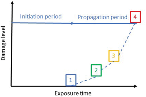
The guidelines apply the conceptual model proposed by Tuutti (Citation1982). is an elaborated version of Tuutti’s model illustrating the progress of corrosion. Steel in concrete is protected by a thin oxide film (a passive film) that is formed spontaneously in the alkaline environment of concrete. Corrosion can start due to carbonation or the ingress of chloride ions, and then various types of damage gradually develop (Bertolini et al., Citation2013). illustrates the initiation period, in which the aggressive agents penetrate into the concrete until depassivation of the steel occurs, and the propagation period, in which corrosion is ongoing until a selected limit state or an accepted degree of damage marking the end of service life is reached.
Figure 3. A schematic representation of the current concept for service life design. The limit states for structures affected by reinforcement corrosion are as suggested in the fib Model Code for Service Life Design 2006 (fib, (Fédération International du Béton), Citation2006): 1) depassivation of the reinforcement; 2) crack formation; 3) spalling of cover; 4) structural collapse. Limit state 1 determines the end of the initiation period. Limit states 2 and 3 are typical for carbonation-induced corrosion. Chloride-induced corrosion will either not manifest or do so very late with crack formation or spalling; the main problem is loss of cross section (invisible because corrosion products remain soluble), which suggests ‘loss of cross section’ as a relevant limit state.
To a large extent, the DuraCrete guidelines formed the basis for the fib Model Code for service life design, which was published in 2006 (fib (Fédération International du Béton), Citation2006), and the corresponding standard, which was published by the International Organization for Standards (ISO) in 2012 (ISO (International Organization for Standards), Citation2012).
3.2. Strategies and design approaches in the fib model code for service life design
The fib Model Code for Service Life Design 2006 (fib (Fédération International du Béton), Citation2006) describes two strategies for durability design, controlling the development of a given deterioration mechanism or basically avoiding it, and three levels of design approach, see . The guidelines for Strategy 1 include carbonation and chloride-induced corrosion initiation, defining limit state functions and failure probabilities, and providing statistical input data for carbonation and chloride ingress, which in many cases cannot be avoided, so that the rate of damage development needs to be controlled. The ISO standard (ISO (International Organization for Standards), Citation2012) also includes limit state functions for freeze/thaw damage, with and without de-icing agents or sea water, and it provides deemed-to-satisfy rules (Level 3) for limiting alkali-aggregate reactions and sulphate attack.
Table 4. Strategies and design approaches for durability design (fib (Fédération International du Béton), Citation2006).
Summarizing the experience of a European designer office, Geiker and Edvardsen (Citation2014) said that ‘the use of the Model Codes and Draft Standard still required specialist knowledge, both for the selection of models and input parameters, and for the assessment of the output. Pre-testing and production monitoring are required as an inherent part of durability design. And inspection and monitoring plans should be established for the verification of applied models and parameters to facilitate proactive maintenance and repair.’ It is our understanding that these comments are still valid and that further improvement in the reliability of durability design requires greater understanding of the mechanisms acting at the level of both materials and structure, further development of generic models, and data collection for both input and model verification. In particular, we see a need to increase our understanding of the impact of materials degradation on structural performance.
3.3. Limit states and acceptance criteria
A central part of durability design is the selection of acceptance criteria, i.e., the limit states and the probability of exceeding these limit states (see ). The greater the consequences (safety, economic, social) of exceeding a limit state, the lower the accepted probability. In the fib Model Code for Service Life Design 2006 (fib (Fédération International du Béton), Citation2006), the recommended values for the probability of collapse are in the range of 10−6–10−4 per year, depending on the consequence. When service life modelling is applied to reinforced structures, time to depassivation is the most-used limit state – presumably because the performance tests and the modelling approaches are most advanced for the estimation of time to depassivation. In the fib Model Code for Service Life Design 2006, the recommended values for probability of failure are 10% for depassivation.
As is reasonable, the accepted probability of exceeding this much less severe limit state is higher than for collapse; however, at present no differentiation is made between the different consequence classes. As design should always ensure that all combinations of limit states and probabilities of failure are fulfilled for a given structure, one common failure probability of depassivation may indicate that a number of design solutions cannot be optimized. The applied failure probability of depassivation should reflect the rate of deterioration at the structural level and the loss of carrying capacity. If the rate of corrosion is negligible, depassivation is a less relevant limit state. On the other hand, if the rate of corrosion is high and the consequences of corrosion are great, the probability of depassivation should be low because corrosion onset will rapidly lead to serious damage. The need for a differentiated probability of failure and a more discriminating use of limit states has recently been debated for carbonation-induced corrosion, where the present use of limit state depassivation works against the use of low clinker blends (Angst et al., Citation2020).
Ignoring the issues mentioned above and assuming that depassivation of reinforcement is a suitable limit state, the next issue is the selection of a suitable limit state value. For chloride-induced corrosion this is a major issue because the critical chloride content varies substantially (Angst et al., Citation2009) and the parameters affecting corrosion initiation are neither fully understood nor their impact sufficiently quantified (Angst et al., Citation2019). Recent work in RILEM TC 262 SCI on the impact of the steel–concrete interface (SCI) indicates that the characteristics of the steel and the moisture load at the SCI have a major influence on the initiation of chloride-induced corrosion (Angst et al., Citation2019). The need for improved understanding of the mechanisms and the methods for their characterization is further discussed in Section 4.1.1 below.
4. Need for model improvement
For design purposes, avoidance strategies are often used for alkali-aggregate reactions and freeze/thaw damage, leaving models for carbonation and chloride-induced corrosion most required. For the assessment of the residual service life of existing structures, additional degradation mechanisms might have to be considered too, increasing the complexity of the problem.
fib and ISO have reached consensus on models for the prediction of the progress of the carbonation front and the ingress of chlorides, but they treat the concrete as a continuum, i.e., they do neither consider cracked concrete nor elemental zonation and depth-dependent changes in chloride binding (Jakobsen et al., Citation2016). Many more questions remain open regarding, corrosion propagation, and concrete cracking. For these limit states no time-dependent models are considered sufficiently mature to achieve international consensus (Helland, Citation2016), but there is no doubt that prediction models are needed that can support the design of new structures as well as the assessment, maintenance, and repair of existing structures (Angst et al., Citation2012; Geiker et al., Citation2019).
Selected improvements needed in service life prediction models and statistical data are discussed below with focus on the prediction of chloride-induced corrosion initiation and propagation.
4.1. Initiation period: time to depassivation of reinforcement
Due to lack of space, the ingress of aggressive substances, including through cracks, will not be covered here. However, it is generally accepted that cracks facilitate ingress of aggressive substances and thus may cause early corrosion onset, so the impact of cracks on corrosion onset and propagation is dealt with in Sections 4.1.1 and 4.2 below. For discussion of carbonation-induced corrosion onset, the reader is referred to a very recent review paper prepared by a task group of RILEM TC 281 CCC (Angst et al., Citation2020).
4.1.1. Corrosion onset – the critical chloride content
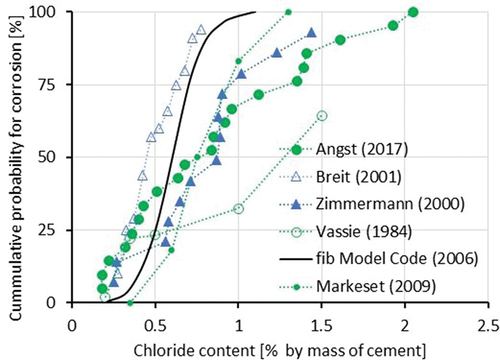
For chloride-induced reinforcement corrosion, the models link corrosion onset to a so-called critical chloride content, Ccrit, which is considered the threshold chloride concentration associated with onset of corrosion (the first pit). Despite numerous studies, the consensus is that Ccrit has no universal value and that the values of Ccrit in a given environment/material combination are statistically distributed (Angst et al., Citation2009). To date, the model codes are based on a (quite narrow) distribution that is based on laboratory experiments (Breit, Citation2001). This assumption can be criticized because the Ccrit values were obtained by potentiostatic polarization and therefore acceleration, and because laboratory samples are more homogeneous than field concrete. Indeed, results from the examination of concrete structures show different values and distributions for Ccrit. For a 37-year-old jetty in Norway, the statistical distribution of the critical chloride content could be described as averaging 0.77% chloride by weight of cement with a coefficient of variation of 32% (Markeset, Citation2009). Recent research in Switzerland determined the critical chloride content of a 40-year-old structure (Angst et al., Citation2017) as having a much broader distribution of Ccrit than indicated by the fib Model Code for Service Life Design 2006 (see ).
Figure 4. Data from the literature on the statistical distribution of chloride threshold values in Portland cement systems. Circles = field data; triangles = laboratory data; solid line = distribution suggested in the fib Model Code for Service Life Design 2006. data from (Angst et al., Citation2017; Breit, Citation2001; Markeset, Citation2009; Vassie, Citation1984; Zimmermann, Citation2000).
A recent publication of RILEM TC 262 SCI attempted to rationalize this broad distribution by focusing on defects at the steel–concrete interface (Angst et al., Citation2017) and the effect of these characteristics on chloride-induced corrosion initiation (Angst et al., Citation2019). One of the conclusions was that it might be difficult to mimic realistic conditions with small laboratory samples; another was that the impact of steel metallurgy and the moisture conditions at the steel–concrete interface appear to be decisive but overlooked factors.
Last but not least, the ‘size effect’ also has to be considered: under identical exposure conditions, larger samples show lower Ccrit than small samples (Angst & Elsener, Citation2017; Li & Sagüés, Citation2004). In addition, it should be noted that the standard deviation markedly decreases with increasing sample size. This size effect is to be expected because the initiation of chloride-induced localized corrosion is a stochastic process that can be linked to ‘weak points’ along the steel–concrete interface. It has been shown that the Ccrit of large samples can be reliably predicted using the weakest link theory based on results from Ccrit distribution measured on small samples (Angst & Elsener, Citation2017).
Considering the weakest link, it should be mentioned that, although cracks are found to facilitate the rapid ingress of aggressive substances, ongoing corrosion at other ‘weak links’ might lead to corrosion not initiating. This was observed in a recent case-study of 25-year-old marine-exposed cracked concrete beams, where corrosion at spacers apparently led to the protection of neighbouring reinforcement (Geiker et al., Citation2021).
To summarize, the poor definition of one of the most decisive parameters, Ccrit, creates severe limitations for service life modelling: small uncertainty in Ccrit can lead to large uncertainty in initiation time. Apart from the statistical distribution of Ccrit, this is a direct consequence of the transport model, intrinsic to which is the way the increase in chloride concentration at the depth of the reinforcement becomes very slow after a few decades. Moreover, the ‘size effect’ on Ccrit has a significant impact on the predicted time to corrosion onset. On the other hand, this could open a way to link materials-science-based evidence with structural engineering considerations and give a more rational meaning to the term ‘probability of corrosion initiation’ (Angst, Citation2018).
4.1.2. Proposed measures to improve the statistical input data for the prediction of chloride-induced corrosion onset
In the opinion of the authors, significant progress can be made in determining the time to onset of corrosion (initiation time) by addressing the problem of how Ccrit can be determined and taking the size effect into account.
New test procedure to determine Ccrit. A new test for critical chloride content is intended to simulate natural conditions (including realistic casting, steel–concrete interface, and the corrosion potential of reinforcement and exposure conditions). In the context of the ongoing discussions in the CEN on standardization in the definition of exposure resistance classes (Von Greve-Dierfeld, Citation2015) (see Section 2.2), the test procedure for chloride ingress is defined in EN 12390–11 (CEN (European Committee for Standardization), Citation2015). This initial characterization of the transport properties of concrete takes up to two years, so the authors conclude that a more realistic chloride threshold test must be feasible. Indeed, a test method based on reinforced concrete cores known as the ‘ETH method’ has been proposed and validated (Angst et al., Citation2017).
Relate Ccrit to structure. The documented influence of the size of the test samples on Ccrit (Angst et al., Citation2011) and therefore on the time of initiation means it is, in principle, possible to link materials science (the size effect in corrosion) to structural engineering. Based on the Ccrit data, Angst (Citation2018) calculated the time to corrosion initiation for various failure probabilities (pf = 3.5%, 10% and 30%, corresponding to the target reliability indices = 0.5, 1.3 and 1.8 commonly used for a serviceability limit state) as a function of the rebar length (). For a corrosion probability of 30%, the calculated time to corrosion depends strongly on the rebar length, whereas for pf < 10% and a rebar length > 0.5 m, the influence is quite small.
Figure 5. Predicted time to corrosion (tini) as a function of rebar length for various failure probabilities (pf = 3.5%; 10% and 30%) based on data from samples from a structure and assuming a cover depth at 50 mm. (Angst, Citation2018).
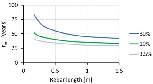
The results plotted for failure probability pf = 30% in indicate that, for a cover depth of 50 mm and after 60 years, we should on average expect corroding sites every 40 cm on every rebar, which gives owners and engineers some basis on which they can decide on the acceptable risk for corrosion.
4.2. Damage propagation
We distinguish damage on three scales: (i) the corrosion propagation of the steel within its concrete environment (Section 4.2.1), (ii) local rust formation causing a volumetric expansion in the steel bars that damages the concrete or local loss of cross section (Section 4.2.2), and (iii) damage to structural elements or to the structure as a whole (Section 4.2.3).
4.2.1. Corrosion propagation of the steel in concrete
The propagation stage () includes the process of corrosion and accumulation of related damage until a limit state is reached and with it the end of the design service life. Many reinforced concrete structures are more than 50 years old, which means that corrosion propagation might be a significant part of their actual or future service life. Moreover, for the durability design of new structures, part of the corrosion propagation period could be explicitly included in the design life if we know the corrosion rate is low or negligible. This corrosion rate, in turn, is governed by the environmental conditions of the structure or the structural member.
Corrosion propagation in carbonated concrete. The corrosion rate of steel in carbonated mortar increases markedly with increasing relative humidity (RH) and is highest in wet conditions – irrespective of binder type or w/b ratio (). This has been confirmed in a literature review (Stefanoni et al., Citation2018) and other studies of steel in carbonated concrete (Revert et al., Citation2019).
Figure 6. Impact of moisture on the corrosion rate of steel in carbonated micro-mortar exposed to constant moisture conditions. The average coefficient of variation (CV) in the measurements was 18%. (Stefanoni et al., Citation2017).
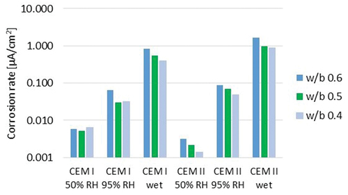
Knowing the corrosion rate of steel in carbonated concrete (for the scientific basis, we refer to Stefanoni et al., Citation2019) will allow the explicit implementation of the corrosion propagation period in service life modelling of reinforced concrete structures. This is crucial for a holistic sustainability assessment of potentially environmentally friendly cement types.
For exposure class XC3 (moderate humidity, see ), where no wetting and drying cycles take place, the expected service life of RC structures can be considered much longer than is usually assumed, because the corrosion rate during the propagation period is either low or very low.
For exposure class XC4 (wetting and drying cycles), the corrosion rate of steel in carbonated concrete is highest in wet conditions and decreases in drying conditions (Stefanoni et al., Citation2020). To model the propagation period of steel in carbonated concrete in exposure class XC4, we would therefore need to know the duration and frequency of wetting events. One approach would be to apply the concept of ‘time of wetness’, as for atmospheric corrosion. There is a ‘weather function’, which describes the meso-climate including the time of wetness, in the full probabilistic model provided in the fib Model Code for Service Life Design 2006 (fib (Fédération International du Béton), Citation2006) and in fib Model Code 2010 (fib (Fédération International du Béton), Citation2010).
Corrosion propagation in the case of localized chloride-induced corrosion. For chloride-induced corrosion, local disruption of the passive film of the reinforcing steel leads to a continuously growing pit that, after some years of corrosion propagation, manifests with a severe loss of reinforcement cross section. Such localized corrosion attacks are governed by rapid pit growth with a self-sustaining mechanism. Moreover, the presence of the pit (anode) in a large area of passive steel (cathode) promotes a macro-cell corrosion that increases the dissolution at the anode and protects the passive film, stabilizing the local attack (Bertolini et al., Citation2013). Furthermore, no solid rust products are formed in the pit, because even small amounts of chloride ions (about 10 mM/l) strongly increase the solubility of iron ions (Sagoe-Crentsil & Glasser, Citation1993). This dissolved iron is diffused and migrates away from the pit into the pore system of the concrete. As a consequence, such localized corrosion attacks will manifest at the surface only at a very late stage. However, they can be located early using half-cell potential mapping (Elsener et al., Citation2003).
For very humid and chloride-contaminated concrete (exposure class XD3), the corrosion rate during the propagation period of localized corrosion is generally indicated as high to very high, ranging from 0.2 to 1 mm/year (Bertolini et al., Citation2013). This broad range is due to variation in concrete humidity, but is also due to the inherent difficulty in determining the localized corrosion rate, both in the laboratory and on structures. Measurements of the corrosion rate on site using the polarization resistance (Rp) technique are difficult to interpret because the size of the anode is unknown (Elsener, Citation1999). Moreover, the applicability of the Rp technique to localized corrosion has been fundamentally questioned (Angst & Büchler, Citation2015). Quantitative results can only be obtained from laboratory or field experiments where the area of localized attack (anode) has been electrically isolated from the passive reinforcement (cathode). Such galvanic currents can be converted to corrosion rates; an example from field tests is shown in (Schiegg, Citation2002).
Figure 7. Loss in diameter measured by galvanic current between an anode isolated from the rest of the reinforcement in a bridge deck. measuring started in January 1998; i.e., months 6, 18, 30 are in mid-summer. anode area 5 cm2. (Schiegg, Citation2002).
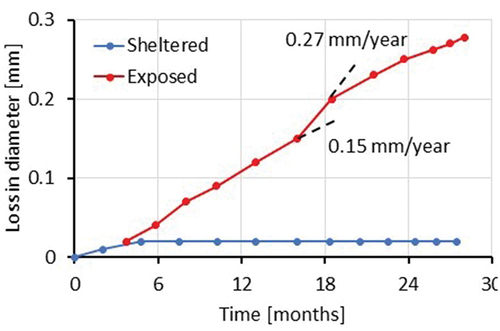
Two types of information can be gathered and generalized: first, a localized corrosion spot in reinforced concrete that is sheltered from rain or splash water (exposure class XD1) will have a corrosion rate < 20 µm/year. If exposed to rain or splash water (exposure class XD3), the corrosion rate will be 5 to 10 times higher () and can reach up to 1 mm/year (Bertolini et al., Citation2013). The second parameter visible is the influence of the seasons; during the long winter-period, the corrosion rate is about half what it is in the summertime.
Corrosion propagation in cracked concrete. The fib Model Code for Service Life Design 2006 (fib (Fédération International du Béton), Citation2006) ranks the impact of cracks on the service life of a structure based on their surface crack width, the orientation of the exposed surface, and the exposure, but provides only rough guidelines. Considering (i) that most concrete elements do contain cracks, (ii) that substantial material and economic resources are used to limit crack width, and (iii) that the impact of cracks on the propagation period is even less known than their impact on the initiation period, it is clear that an improved understanding of the impact of cracks on both corrosion initiation and corrosion propagation is greatly needed. This is accentuated by the increasing requirements for the service life of concrete structures in harsh environments, e.g., coastal bridges.
Very recent experimental data (Boschmann Käthler et al., Citation2021) demonstrates that the corrosion rate in cracked concrete depends on the duration of wetting and the duration and harshness of drying. The lower the ambient RH during drying, the faster the cracks dry, which reduces the corrosion rate in the periods between wetting events. This is why the concept of ‘time of wetness’ was suggested. Such an approach resembles the prediction of the impact of exposure on carbonation progress, and it will facilitate the quantification of the impact of cracks on corrosion propagation. Predicting the long-term impact of cracks it should be kept in mind that self-healing of cracks (Danner et al., Citation2019) could reduce their potential detrimental long-term impact, especially in marine environments.
Field observations on the impact of cracks on corrosion are non-conclusive. This might partly be explained not only by the ability of cracks to self-heal, which varies with exposure and orientation, but also by ongoing corrosion at ‘weaker links’ (Geiker et al., Citation2021), see Section 4.1.1.
4.2.2. Local damage formation
The local damage from corrosion differs markedly when we compare corrosion due to carbonation, resulting in limit states 2 or 3 (), and chloride-induced corrosion, which results in limit state 4.
Carbonation-induced corrosion manifests as uniform rust formation on the steel surface. The rate of corrosion propagation (see Section 4.2.1) determines the amount of rust produced in a given time interval. As the volume of rust is 2–3 times greater than that of steel, an expansive pressure is applied to the concrete cover resulting in cracks (e.g., as delamination) and later spalling of the cover.
Traditional structural designs are based on cross-sectional strength verifications of the reinforced concrete members. There are several aspects to the effect of corrosion propagation on the load-carrying capacity of the cross section of a structural element. The cross-sectional steel area diminishes with time. This applies to both longitudinal reinforcements and stirrups. The volumetric expansion of the rust products can lead to a reduction in the cross-sectional area of the concrete. If the concrete spalls on the compressive side, this decreases the internal lever arm. Corrosion-induced concrete cracking, typically aligned with the reinforcement bars, leads to the concrete having reduced effective compressive strength. And reduced confinement will influence the interaction between concrete and reinforcement. All these effects together will lead to reductions in the moment, shear, and anchorage capacities of the cross section.
Chloride-induced corrosion leads to a localized loss in reinforcement cross section (see Section 4.2.1), and the corrosion rate in the pit determines the progress of the cross-section loss. Over time, this not only influences the strength, but also the ductility of the reinforcement bars. The ‘notch effect’ means this reduction will be more pronounced than for carbonation-induced corrosion with the same loss of steel section. Since both longitudinal reinforcement and stirrups could suffer from pitting corrosion, localized corrosion will lead to reductions in both the moment and the shear capacity of a cross section of the reinforced concrete (RC) member. No spalling due to rust formation will occur, so the cross section of the RC member will not be altered and the compressive strength of the concrete will not be affected, which means no further reductions in the moment and shear capacity will occur. The main concern is the loss in the ductility of the reinforcement, and therefore of the RC member. The loss of ductility might mean there is no warning before the RC member ultimately fails.
A traditional design approach to address both carbonation and chloride-induced corrosion is to base a structural assessment of cross-sectional capacities on worst-case scenarios for each cross section. This will reveal the structural effects of steel corrosion in the propagation phase for every cross section, and critical cross sections could then be identified. However, this approach will lead to overly conservative assessments. This is particularly the case for chloride-induced (localized) corrosion where the statistical distribution of pits along bars and between bars will hamper worst-case cross-sectional verification the most.
4.2.3. Structural impact of materials degradation
Lifting our gaze from the purely cross-sectional level to the structural scale offers the possibility of making assessments less conservative. This is because it enables us to include the effect of spatial corrosion distributions and to consider stress and force redistribution effects within the structure, which may reveal hidden structural capacities. However, assessments at the structural level are less straightforward, even for sound structures, let alone for deteriorating structures. We will need to be able to give more guidance to structural engineers on how they can incorporate material degradation effects into their assessment of structures, ultimately leading to clear-cut codes.
One currently ongoing activity to address this challenge is the update of the fib Model Code 2010 (fib (Fédération International du Béton), Citation2010). In a major effort, the fib is working towards a general code for both new and existing concrete structures, the fib Model Code 2020 (Matthews et al., Citation2018). This will take sustainability as a fundamental requirement. While this is certainly commendable, this tremendous effort will not be completed by the time the code is issued. The code will be incomplete, and the treatment of deteriorated materials will not be equally applicable, equally detailed, and equally accepted. The result will be an early-stage design code that requires follow-up.
Two fib bulletins exemplify the current stage in the development of design codes for existing structures. The first one is the recent fib bulletin 80 (Caspeele et al., Citation2016) by the fib task group TG3.1, which focuses on full-probabilistic and semi-probabilistic methods for existing structures and sets a consistent framework for assessing existing structures. The common practice is that existing structures are verified using the same procedures as for the design of new structures. These procedures are based on the partial factor method. It is generally believed that such assessments are conservative. Bulletin 80 now details a comprehensive evaluation method from a risk and reliability point of view. The bulletin provides a fundamental basis for evaluating and adjusting partial factors, which is compatible with the Eurocode. The essential idea is that the design rules for new structures can still be used, provided that the engineer takes actual information on the material parameters and possible local structural defects into account. The most notable restriction of the bulletin is that the methods presented are not generally applicable for deteriorating structures (although some suggestions are given).
The second one is the draft of a new fib bulletin (fib, in preparation) by the fib task group TG3.2, which focuses on modelling the structural performance of existing concrete structures. It starts with the notion that deterioration will reduce the structural resistance of a structure over time, and a combined increase in the maximum load will further reduce structural safety. Rather than giving a solid probabilistic framework for assessing deteriorated structures (a fundamental task yet to be carried out), this new bulletin emphasizes the so-called residual bearing capacities of existing structures. By using advanced levels of approximation, that is by using more advanced and costly modelling approaches, substantial extra capacities can be demonstrated.
The two bulletins underline the immense task facing the ongoing development of design codes for existing and perhaps deteriorating structures. Kioumarsi et al. (Citation2016) demonstrated how the probability of failure of a simply supported reinforced concrete beam suffering from both uniform and pitting corrosion could be assessed. It requires advanced full 3D nonlinear finite-element modelling and statistical data for the extent and location of the corrosion. The correlation of the location of corrosion pits between adjacent reinforcement bars then becomes the dominant factor for failure capacity. As such, statistical knowledge about the spatial distribution of pits, like the size effect study mentioned in Section 4.1.1 and its physical interpretation in Section 4.1.2, is the crucial link between material and structural modelling. We emphasize that the study by Kioumarsi et al. is truly at an academic level. For real-life existing structures, there is a need to facilitate advanced structural models (i.e., to adopt high levels of approximation) that are well-embedded in safety formats that allow the inclusion of all relevant measurement data in an objective way.
5. Perspectives
To support the development of solutions for concrete structures that will help society and industry meet national and international sustainability goals and commitments, we need to focus on the overall impact of structures over their entire service life, and we need to design and operate them taking into consideration both engineering and sustainability limit states (Geiker et al., Citation2019). These concerns are also reflected in the drafting of the fib Model Code 2020 (Matthews et al., Citation2018). It is essential that models with a sound scientific fundament in mechanistic understanding become available as the basis for design and management tools and for the further development of standards and regulations. Traditionally, new design and maintenance approaches are explored in connection with large infrastructure projects, where design optimization is motivated by the scale of the project and its demanding requirements, and supported by a professional project organization. However, since cement and concrete are mostly used for simpler structures and for non-structural purposes, regulations need to support such sustainable solutions in general.
5.1. Research needs
We see the need for research that will support the development of multiple solutions: novel structural designs with reduced use of concrete and reinforcement; novel methods of construction ensuring consistently high quality and limiting non-conformance; novel structural assessment, maintenance, and repair strategies that will ensure the optimized preservation of existing structures; novel concretes with reduced use of cement; and novel cements with reduced use of Portland clinker. To facilitate all this, we need mechanism-based multi-scale prediction and assessment tools covering both new and existing concrete structures. Parametric modelling will allow up-front assessment of alternative design and re-design solutions, and help identify the determining factors for meeting engineering limit states and/or sustainability limit states. Advanced structural analysis of existing structures and digital information flow will ensure traceable data and provide the background for extending their service life. Furthermore, we see digital twins as useful ways of collecting all the necessary data in an accessible form for the assessment of engineering and sustainability performance.
The generic character of the multi-scale mechanism-based models is important, especially considering the continuing development in cement compositions and the variation in exposure, including climate changes. Such generic models will greatly increase the likelihood of new sustainable solutions, both for the design of new structures and the assessment, maintenance and repair of existing structures (Geiker et al., Citation2017, Citation2019).
5.2. Next generation service life models
Currently, the time to depassivation is used as limit state in the fib Model Code for Service Life Design (fib (Fédération International du Béton), Citation2006), and the time to depassivation is linked to the probability of failure. Exposure-dependent damage development (see Section 4) is not reflected in the accepted probability of failure, because currently only one failure probability (10%) is recommended. We propose to include the propagation period explicitly in the next models for service life design by either (i) adopting the probability of depassivation () or (ii) explicitly calculating the rate of damage development.
Figure 8. Suggested differentiation of the probability of failure for depassivation based on corrosion type (uniform vs localized corrosion), corrosion rate, and the implications of corrosion. Carbonation-induced corrosion (XC) typically leads to cracking and spalling, while chloride-induced corrosion (XD) may not be visually identified before much greater structural damage occurs. For the exposure indicated by exposure classes according to EN 206, see .
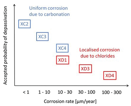
The rational and scientific basis behind this is that the corrosion rate of steel in concrete after depassivation varies over orders of magnitude (see the x-axis in ). There are many exposure conditions where the corrosion rate of the reinforcement after depassivation is low or very low; for example, the corrosion rate of steel in carbonated concrete in environments with a relative humidity < 90% (XC3 according to EN 206) can be considered as low and becomes negligible in environments with RH < 80%. Depassivation of the steel in such conditions is not a suitable limit state and the probability of depassivation can be much higher than 10%. On the other hand, chloride-induced localized corrosion of the reinforcing steel in a structure exposed to rain and splash water (XD4 according to EN 206) has been shown to proceed with a high to very high corrosion rate (). Moreover, the damage can only be detected at a very late stage. Such cases are very dangerous and have to be avoided. As a consequence, the accepted probability of depassivation should be very low.
It should be noted that in this concept (), the probability of depassivation can be increased or decreased according to the structural relevance of the corroding reinforcement; for important primary reinforcement, the probability of depassivation should be lower than for less important secondary reinforcement. In addition to the type and rate of damage development and its structural impact, the consequence of failure must also be considered. The consequence of a potential failure is reflected in the fib Model Code for Service Life Design (fib (Fédération International du Béton), Citation2006) in the recommended maximum values for the probability of collapse, but currently not for the limit state depassivation.
6. Conclusions
The European approach to durability design is in continuous development. To overcome the inconsistencies of the current European prescriptive approach, a new durability design concept, similar to strength classes, has recently been proposed: ‘exposure resistance classes’. For large-scale structures in harsh environments, where the structures considered and the owner’s requirements for service life go beyond the standards, other concepts have been used, from the multi-stage protection strategy applied for the Great Belt Link, to the full probabilistic approach in the fib Model Code for Service Life design.
We emphasize that both potential prescriptive requirements and engineering limit states used for durability design should address performance at the structural level. Different types of corrosion cause very different damage development; carbonation-induced uniform corrosion generally results in cracking and spalling, whereas chloride-induced localized corrosion in the most loaded parts of structural elements may impair structural safety. It is therefore essential that designers understand the basic deterioration mechanisms and know about the potential types and rates of damage development. In this context, we propose that the next generation of service life models should explicitly include the propagation period or, alternatively, that the accepted probability of depassivation should reflect the types of corrosion and their structural implications. Sustainability-focused innovation is required in the construction industry to meet future climate goals, and both engineering limit states and sustainability limit states need to be considered. Generic multi-scale mechanism-based models will greatly increase the likelihood of new sustainable solutions and allow for up-front parametric modelling for assessment of the entire life-cycle impact of alternative design solutions.
Acknowledgments
The first author should like to express her sincere acknowledgement of the late Steen Rostam at COWI; he was an inspiring mentor and an including colleague. The first author further acknowledges discussions with Carola Edvardsen at COWI, Steinar Helland (private company), Stefanie von Greve-Dierfeld at TFB AG, Tor Arne Hammer at SINTEF, Mike Lepech at Stanford University, Henrik Stang and Alex Michel at DTU, Ueli Angst at ETH, and her colleagues at NTNU: Terje Kanstad, Jan Arve Øverli, Klaartje De Weerdt, and Stefan Jacobsen.
Disclosure statement
No potential conflict of interest was reported by the author(s).
Additional information
Notes on contributors
M. R. Geiker
M. R. Geiker is a professor at the Norwegian University of Science and Technology (NTNU), Department of Structural Engineering, Norway. She studied chemical engineering at the Technical University of Denmark (DTU) and has worked 15 years in the industry and more than 15 years in academia. Her research interests include the structure-property relationship of cementitious materials in their fresh, hardening and hardened state, durability, service life prediction, and sustainability.
M. A. N. Hendriks
M. A. N. Hendriks is a professor at the Delft University of Technology (TU Delft), Faculty of Civil Engineering and Geosciences, the Netherlands, and a professor at the Norwegian University of Science and Technology (NTNU), Department of Structural Engineering, Norway. He studied mechanical engineering at TU Eindhoven, and received his PhD from TU Eindhoven, the Netherlands in 1991. His research interests include the nonlinear finite- element analysis of reinforced concrete structures, structural reliability analysis, and the effects of deterioration on structural safety and service life.
B. Elsener
B. Elsener is a professor at the University of Cagliari, Department of Chemical and Geological Science, Italy and a former professor at ETH Zürich, Institute for Building Materials, Zürich, Switzerland. He studied materials science at the Department of Chemistry at ETH Zürich and received his PhD from ETH Zürich, Switzerland in 1982. His research interests include the corrosion of metals in general, electrochemical techniques, sensors, the condition assessment and durability of reinforced and post-tensioned structures, and the corrosion of steel in concrete.
References
- Angst, U. (2018). The importance of the size effect in corrosion of steel in concrete for probabilistic service life modeling. In: 6th International Symposium on Life-Cycle Civil Engineering (IALCCE 2018), pp.1313–1319, Ghent, Belgium London: CRC Press/Balkema.
- Angst, U., Boschmann, C., Wagner, M., & Elsener, B. (2017). Experimental protocol to determine the chloride threshold value for corrosion in samples taken from reinforced concrete structures. Journal of Visualized Experiments: JoVE, 126, 56229. doi:10.3791/56229
- Angst, U., & Büchler, M. (2015). On the applicability of the Stern–Geary relationship to determine instantaneous corrosion rates in macro-cell corrosion. Materials and Corrosion, 66(10), 1017–1028. doi:10.1002/maco.201407997
- Angst, U., & Elsener, B. (2017). The size effect in corrosion greatly influences the predicted life span of concrete infrastructures. Sci Adv, 3(8), e1700751. doi:10.1126/sciadv.1700751
- Angst, U., Elsener, B., Larsen, C. K., & Vennesland, Ø. (2009). Critical chloride content in reinforced concrete – A review. Cement and Concrete Research, 39(12), 1122–1138. doi:10.1016/j.cemconres.2009.08.006
- Angst, U., Geiker, M. R., Alonso, M. C., Polder, R., Isgor, O. B., Elsener, B., Wong, H., Michel, A., Hornbostel, K., Gehlen, C., François, R., Sanchez, M., Criado, M., Sørensen, H., Hansson, C., Pillai, R., Mundra, S., Gulikers, J., Raupach, M., Pacheco, J., & Sagüés, A. (2019). The effect of the steel–concrete interface on chloride-induced corrosion initiation in concrete: A critical review by RILEM TC 262-SCI. Materials and Structures, 52(4), 88. doi:10.1617/s11527-019-1387-0
- Angst, U., Hooton, R. D., Marchand, J., Page, C. L., Flatt, R. J., Elsener, B., Gehlen, C., & Gulikers, J. (2012). Present and future durability challenges for reinforced concrete structures. Materials and Corrosion, 63(12), 1047–1051. doi:10.1002/maco.201206898
- Angst, U., Moro, F., Geiker, M. R., Kessler, S., Beushausen, H., Andrade, C., Lahdensivu, J., Köliö, A., Imamoto, K., von Greve‐Dierfeld, S., & Serdar, M. (2020). Corrosion of steel in carbonated concrete: Mechanisms, practical experience, and research priorities – A critical review by RILEM TC 281‐CCC. RILEM Technical Letters, (Vol), 5. doi:10.21809/rilemtechlett.2020.127
- Angst, U., Rønnquist, A., Elsener, B., Larsen, C. K., & Vennesland, Ø. (2011). Probabilistic considerations on the effect of specimen size on the critical chloride content in reinforced concrete. Corrosion Science, 53(1), 177–187. doi:10.1016/j.corsci.2010.09.017
- Bertolini, L., Elsener, B., Pedeferri, P., Redaelli, E., & Polder, R. B. (2013) Corrosion of steel in concrete: Prevention, diagnosis, repair. 2nd. WILEY-VCH, Weinheim; Germany. ISBN: 978-3–527–33146–8
- Boschmann Käthler, C., Angst, U., Ebell, G., & Elsener, B. (2021). Chloride-induced reinforcement corrosion in cracked concrete: The influence of time of wetness on corrosion propagation. Corrosion Engineering, Science and Technology, 56(1), 1–10. doi:10.1080/1478422X.2020.1789371
- Breit, W. (2001). Critical corrosion inducing chloride content – State of the art and new investigation results. In Thielen, G., Betontechnische Berichte 1998–2000 (pp. 631–637). Vbt Verlag Bau U. Technik, Erkrath, Nordrhein-Westfalen, Germany.
- Caspeele, R., Steenbergen, R., & Sykora, M. (2016). Partial factor methods for existing concrete structures, Fédération International du Béton (fib) Bulletin No. 80. Wilhelm Ernst & Sohn, Verlag für Architektur and technische Wissenschaften GmbH & Co. KG. 10.35789/fib.BULL.0080
- CEN (European Committee for Standardization). (2004). EN–1992–1–1: Eurocode 2, Design of concrete structures – Part 1–1: General rules and rules for buildings.
- CEN (European Committee for Standardization). (2009). EN 13670: Execution of concrete structures.
- CEN (European Committee for Standardization). (2013). EN 206: Concrete – Specification, performance, production and conformity.
- CEN (European Committee for Standardization). (2015). EN 12390–11: Testing hardened concrete – Part 11: Determination of the chloride resistance of concrete, unidirectional diffusion.
- Crete, D. (2000). DuraCrete – final technical report. general guidelines for durability design and redesign/probabilistic performance based durability design of concrete structures. DuraCrete Report BE93–1347/R17, CUR, Gouda, The Netherlands, 139
- Danner, T., Hornbostel, K., Strømme, Ø., & Geiker, M. R. (2019). Self-healing and Chloride Ingress in Cracked Cathodically Protected Concrete Exposed to Marine Environment for 33 Years, NTNU, Trondheim. Norway: ISBN. 31. 978–82–7482–119–4
- Elsener, B. (1999). Corrosion Rate of Steel in Concrete – From Laboratory to Reinforced Concrete Structures. In J. Mietz, B. Elsener, & R. Polder (Eds.), Corrosion of Reinforcement in Concrete – Monitoring, Prevention and Rehabilitation (pp. 125–140). Brussels, Belgium: EFC Publication Nr. 25, CRC Press London. Published as E-book (2020). https://doi.org/10.1201/9781003076957
- Elsener, B., Andrade, C., Gulikers, J., Polder, R., & Raupach, M. (2003). Half-cell potential measurements – Potential mapping on reinforced concrete structures. Materials and Structures, 36(7), 461–471. doi:10.1007/BF02481526
- fib (Fédération International du Béton). (2006). fib model code for service life design – bulletin 34, 116.
- fib (Fédération International du Béton). (In preparation). Modelling of structural performance of existing concrete structures, unpublished fib Bulletin. fib (Fédération International du Béton). (2010). fib 2010 Model Code – Bulletins 55 and 56, 311.
- Geiker, M. R., Danner, T., Revert, A. B., & Hornbostel, K. (2021). 25 years of field exposure of pre-cracked concrete beams; combined impact of spacers and cracks on reinforcement corrosion. Construction and Building Materials, 286, 122801. doi:10.1016/j.conbuildmat.2021.122801
- Geiker, M. R., & Edvardsen, C. (2014). Service life design of reinforced concrete structures, developments in the Danish approach. In: Proceedings of the 3rd International Conference on Service Life Design for Infrastructure. Keynote Speech, Zhuhai, China, (pp. 59). Tongji University.
- Geiker, M. R., Michel, A., Lepech, M. D., Wu, J., & Stang, H. (2017). Multi-scale and multi-physics deterioration modelling for design and assessment of reinforced concrete structures. RILEM Technical Letters, 2, 119–128. doi:10.21809/rilemtechlett.2017.49
- Geiker, M. R., Michel, A., Stang, H., & Lepech, M. D. (2019). Limit states for sustainable reinforced concrete structures. Cement and Concrete Research, 122, 189–195. doi:10.1016/j.cemconres.2019.04.013
- Geiker, M. R., Michel, A., Stang, H., Vikan, H., & Lepech, M. (2018). Design and maintenance of concrete structures requires both engineering and sustainability limit states. In: International Symposium on Life-Cycle Civil Engineering (IALCCE 2018), pp. 987–991, Ghent, Belgium, London, CRC Press/Balkema.
- Helland, S. (2013). Design for service life: Implementation of fib Model Code 2010 rules in the operational code ISO 16204. Structural Concrete, 14(1), 10–18. doi:10.1002/suco.201200021
- Helland, S. (2016). Performance-based service life design in the 2021 version of the European concrete standards – Ambitions and challenges. Keynote lecture at: fib Conference, Cape Town, South Africa. ISBN. 978–2–88394–121–2
- ISO (International Organization for Standards). (2012). ISO 16204: Durability – Service Life Design of Concrete Structures.
- Jakobsen, U. H., De Weerdt, K., & Geiker, M. R. (2016). Elemental zonation in marine concrete. Cement and Concrete Research, 85, 12–27. doi:10.1016/j.cemconres.2016.02.006
- Kioumarsi, M. M., Hendriks, M. A. N., Kohler, J., & Geiker, M. R. (2016). The effect of interference of corrosion pits on the failure probability of a reinforced concrete beam. Engineering Structures, 114, 113–121. doi:10.1016/j.engstruct.2016.01.058
- Li, L., & Sagüés, A. A. (2004). Chloride corrosion threshold of reinforcing steel in alkaline solutions – effect of specimen size. Corrosion, 60(2), 195–202. doi:10.5006/1.3287721
- Markeset, G. (2009). Critical chloride content and its influence on service life predictions. Materials and Corrosion, 60(8), 593–596. doi:10.1002/maco.200905288
- Matthews, S., Bigaj-van Vliet, A., Walraven, J., Mancini, G., & Dieteren, G. (2018). fib Model Code 2020: Towards a general code for both new and existing concrete structures. Structural Concrete, 19(4), 969–979. doi:10.1002/suco.201700198
- Polder, R. B., Peelen, W. H. A., & Courage, W. M. G. (2012). Non‐traditional assessment and maintenance methods for aging concrete structures – Technical and non‐technical issues. Materials and Corrosion, 63(12), 1147–1153. doi:10.1002/maco.201206725
- Revert, A. B., Hornbostel, K., De Weerdt, K., & Geiker, M. R. (2019). Macrocell corrosion in carbonated portland and portland-fly ash concrete – contribution and mechanism. Cement and Concrete Research, 116, 273–283. doi:10.1016/j.cemconres.2018.12.005
- Rostam, S. (1993). Service life design – The European approach. ACI Concrete International, 15(7), 24–32.
- Sagoe-Crentsil, K. K., & Glasser, F. P. (1993). “Green rust”, iron solubility and the role of chloride in the corrosion of steel at high pH. Cement and Concrete Research, 23(4), 785–791. doi:10.1016/0008-8846(93)90032-5
- Schiegg, Y. (2002). Online-Monitoring zur Erfassung der Korrosion der Bewehrung von Stahlbetonbauten, PhD thesis, ETH Zürich. 10.3929/ethz-a-004319266
- Stefanoni, M., Angst, U., & Elsener, B. (2017). Relative importance of corrosion rate and exposure condition on the practical use of new environmentally friendly binders. In: Proceedings of the 1st International Conference on Construction Materials for Sustainable Future, Zadar, Croatia, 19–21 April 2017, https://www.researchgate.net/publication/320703132
- Stefanoni, M., Angst, U., & Elsener, B. (2018). Corrosion rate of carbon steel in carbonated concrete – A critical review. Cement and Concrete Research, 103, 35–48. doi:10.1016/j.cemconres.2017.10.007
- Stefanoni, M., Angst, U., & Elsener, B. (2019). Kinetics of electrochemical dissolution of metals in porous media. Nature Materials, 18(9), 942–947. doi:10.1038/s41563-019-0439-8
- Stefanoni, M., Angst, U., & Elsener, B. (2020). The mechanism controlling corrosion of steel in carbonated cementitious materials in wetting and drying exposure. Cement and Concrete Composites, 113, 103717. doi:10.1016/j.cemconcomp.2020.103717
- Tuutti, K. (1982). Corrosion of steel in concrete, PhD thesis, Kungliga Tekniska Högskolan (KTH) in Stockholm. http://lup.lub.lu.se/record/3173286
- Vassie, P. (1984). Reinforcement corrosion and the durability of concrete bridges. Proceedings of the Institution of Civil Engineers, 76(3), 713–723. doi:10.1680/iicep.1984.1207
- Von Greve-Dierfeld, S. (2015). Bemessungsregeln zur Sicherstellung der Dauerhaftigkeit XC-exponierter Stahlbetonbauteile, PhD thesis, Technical University of Munich, https://d-nb.info/1079655123/34
- Von Greve-Dierfeld, S., & Gehlen, C. (2016a). Performance based durability design, carbonation part 1 – Benchmarking of European present design rules. Structural Concrete, 17(3), 309–328. doi:10.1002/suco.201600066
- Von Greve-Dierfeld, S., & Gehlen, C. (2016b). Performance-based durability design, carbonation part 2 – Classification of concrete. Structural Concrete, 17(4), 523–532. doi:10.1002/suco.201600067
- Von Greve-Dierfeld, S., & Gehlen, C. (2016c). Performance-based durability design, carbonation part 3: Partial safety factor (PSF) approach and a proposal for revision of deemed-to-satisfy rules. Structural Concrete, 17(5), 718–728. doi:10.1002/suco.201600085
- Zimmermann, L. (2000). Korrosionsinitiierender Chloridgehalt von Stahl in Beton, PhD thesis, ETH Zürich, 10.3929/ethz-a-004037943