
Abstract
The steerable catheter refers to the catheter that is manipulated by a mechanism which may be driven by operators or by actuators. The steerable catheter for minimally invasive surgery has rapidly become a rich and diverse area of research. Many important achievements in design, application and analysis of the steerable catheter have been made in the past decade. This paper aims to provide an overview of the state of arts of steerable catheters. Steerable catheters are classified into four main groups based on the actuation principle: (1) tendon driven catheters, (2) magnetic navigation catheters, (3) soft material driven catheters (shape memory effect catheters, steerable needles, concentric tubes, conducting polymer driven catheters and hydraulic pressure driven catheters), and (4) hybrid actuation catheters. The advantages and limitations of each of them are commented and discussed in this paper. The future directions of research are summarized.
1. Introduction
Minimally invasive surgery (MIS) utilizes image-guided procedures to diagnose and treat diseases in nearly every organ system, and MIS has revolutionized surgery in the last two decades. By minimizing the physical trauma to the patient, MISs can reduce infection rate and recovery time considerably and it can also allow shortening a hospital stay of the patients. One of the common tools used in MIS, in interventional radiology in particular, is the catheter which is a long, thin and flexible tube or wire. The catheter is inserted into the vascular system, gastrointestinal tract and airway for both diagnosis and treatment. Currently, the majority of MIS procedures are performed manually with the so-called deflectable or conventional catheters. Such catheters have a limited range of motion and flexibility and much rely on the operators’ skill and experience to maneuver the catheter tip to reach and interact the target site in a stable manner. The complexity of the anatomy of the pathway and target site and the lack of information of the contact force are responsible for some difficulty in the operation of catheters in terms of dexterity, safety and stability (inappropriately leading to failures of the operation).
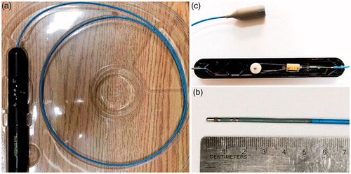
The steerable catheter refers to the catheter that is manipulated by a mechanism which may be driven by operators or by actuators (i.e., automatically). The steerable catheter has thus many advantages over the conventional catheter. The deflection of the distal tip of the steerable catheter is more controbalbe with a possibility of remote control. A typical steerable catheter with its control unit is shown in , in which the distal tip of the catheter can be deflected by a pair of tendons. By comparing the steerable catheter with the conventional catheter, the main advantages of the steerable catheter are the improved accessibility to the difficult anatomy, the improved catheter stability in opertion, the then reduced fluoroscopy times and the then decreased total radiation exposure to both patients and physicians [Citation1–4].
Figure 1. Bard Stinger Ablation Catheter and its control unit (a) the catheter with the control unit; (b) the distal tip of the catheter; (c) the inside of the control unit.
The technology for the steerable catheter has been advanced greatly in the past decade. The commercial products of steerable catheters and robotic catheters (i.e., more advanced steerable cathteters) are available, such as Polaris XTM Steerable Diagnostic Catheters (Boston Scientific Inc., Marlborough, USA), Artisan Extend Control Catheter (Hansen Medical Inc., Mountain View, USA), and Niobe® Magnetic Navigation System (Stereotaxis Inc., St. Louis, USA). A number of minimally invasive clinical applications benefit from steerable catheters, including cardiac surgery [Citation5,Citation6], (Stereotaxis 2016), vascular surgery [Citation7–9], aneurysm surgery [Citation10,Citation11], neurosurgery [Citation12,Citation13], arthroscopy [Citation14,Citation15] and intrauterine fetal surgery [Citation16,Citation17] and so on. It is noted that each application of the steerable catheter is subjected to a different constraint but each plays the same function. The concept of the constraint and function is widely discussed in the engineering design research community and is thus referred to (Fan et al. 2015).
Steerable catheters can be viewed as a kind of hyper-redundant robots or manipulators and differ from the so-called continuum manipulator. A continuum manipulator refers to a continuously bending manipulator made by elastic materials, which does not contain any rigid link to a generic function – i.e., the motion and force. Note that the device that fulfils the motion and force transfer is called mechanism [Citation18]. One example of the continuum manipulator in medical devices is the colonoscope [Citation19,Citation20]. The continuum manipulator is similar to but distinct from the hyper-redundant robot in that the former does not contain any rigid link while the latter contains rigid links (i.e., a hybrid mechanism [Citation21–23] or system in a more general sense in engineering [Citation24]). As such, continuum manipulators are inherently compliant and articulate. Details of the continuum manipulators may be referred to the review articles [Citation25–27].
The steerable catheter needs to meet the following requirements: (1) The diameter of the catheter is strictly limited due to their working environments, e.g., vascular system, gastrointestinal tract, airway or man-made pathway (e.g., the inner pathway of the endoscopy); (2) The catheter is expected to have a high degree of dexterity in order to reach any intricate target site in the “channel”; (3) The catheter is expected to have a proper stiffness for resisting the force, coming from the channel (the high stiffness of the catheter may provoke injuries, while the low stiffness of the catheter may not be able to perform a force-compliant task well owing to an insufficient tip stability of the catheter); (4) The material of the catheter is expected to be biocompatible (in mechanical, thermal, and biochemical) [Citation28] and sterilizable; (5) The magnetic compatibility is expected if the catheter is used in the magnetic resonance imaging (MRI) environment; (7) The safety and cost of the catheter are two important design constraints; (8) The catheter is expected to be intuitive and easy to operate.
This paper provides a review of the steerable catheter with the goal to identify a gap between what is required and the current state of the steerable catheter. The review differs from the one conducted by Ali et al. [Citation29] in several aspects: (1) the scope of applications in their revew only covers cardiology while our review assumes a broad scope of applications; (2) the criterion they employed to classify steerable catheters is how the tip force is generated, which makes them classify the steerable cathether into two categories, namely direct force generation and indiec force generation, while our review focuses on the working or actuation principle of the steerable catheter.
The remaining part of the paper is organized in the following. In Section 2, steerable catheters and their classification based on their actuation mechanism or principle are presented. In Section 3, a comparison of different types of steerable catheters in terms of the safety, cost, performance, and size of catheters is presented. Conclusions along with discussion of the future research challenges of the steerable catheter are given finally in Section 4.
2. Classifications of steerable catheters
Steerable catheters can be classified in several ways. For instance, steerable catheters can be classified based on the actuation principle or driving principle into the tendon-driven catheter, magnetic navigation catheter, soft material driven catheter, and hybrid actuation catheter. Based on the number of sections where actuators stay, steerable catheters can be classified into the single-section and multi-sections. Based on the workspace, steerable catheters can be classified into the planar and spatial ones. It is noted that catheters can also be classified upon their intended medical applications, particularly characterized with their diameter, length, shape of the tip, hydrophilic coating, with or without lumen, and torquabiltiy/stiffness. The detailed information of the selected steerable catheters can be found in . In this paper, the classification of steerable catheters based on the actuation principle is focused on.
Table 1. Comparisons of some typical steerable catheters in the literature.
2.1. Tendon-driven catheters
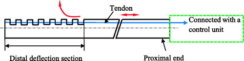
One of the most popular actuation principles is that a set of antagonistic tendons is used to control the orientation of the distal tip of the steerable catheter (). Most of this kind of steerable cathethers have a single flexible backbone that supports the tendons. The backbone is made up of a variety of materials, such as springs, elastic tubes and braided polymer tubes and fabricated using the laser-machined slotting patterns. Among these materials, the super-elastic material nitinol (NiTi) alloy is often used. The tendons are placed at equally spaced intervals along with the backbone and the structure of the tendons makes the shape of the backbone approximate a circular arc. The tendons at the proximal part of the catheter are controlled by the actuation unit which is further controlled by operators ().
Figure 2. Schematic diagram of the structure of the tendon-driven steerable catheter. (The red arrows indicate the movement of tendon and the deflection of the distal section)
2.1.1. Single-section
The single-section tendon-driven catheter can have one to four tendons. The locations of the tendons in the manipulators are shown in . The simplest tendon-driven catheter is composed of one backbone and one or two tendons, e.g., Polaris XTM Steerable Diagnostic Catheter (single tendon) and SteeroCath-Dx™ Bidirectional Steerable Diagnostic Catheter (a pair of tendons) by Boston Scientific Inc. [Citation5]. The similar design of the steerable catheter can be found in [Citation35,Citation36,Citation38].
Figure 3. Location and number of tendons in the tendon-drive catheters. (a) The catheter is driven by one tendon and examples can be found in [Citation5,Citation35–37]; (b) The catheter is driven by a pair of tendons which are placed in 180° and examples can be found in [Citation15,Citation38,Citation39]; (c) The catheter is driven by three tendons placed 120° apart and examples can be found in [Citation40,Citation41]; (d) The catheter is driven by four orthogonally spaced tendons and examples can be found in [Citation16,Citation42,Citation43].
![Figure 3. Location and number of tendons in the tendon-drive catheters. (a) The catheter is driven by one tendon and examples can be found in [Citation5,Citation35–37]; (b) The catheter is driven by a pair of tendons which are placed in 180° and examples can be found in [Citation15,Citation38,Citation39]; (c) The catheter is driven by three tendons placed 120° apart and examples can be found in [Citation40,Citation41]; (d) The catheter is driven by four orthogonally spaced tendons and examples can be found in [Citation16,Citation42,Citation43].](/cms/asset/49b1bef9-4cf2-471f-95b3-a095a6f4d884/icsu_a_1526972_f0003_b.jpg)
To the steerable catheter used for the applications such as diagnosis and radiofrequency ablation (RFA) of tumors [Citation44,Citation45], there is no central open lumen (i.e., inner channel) in the catheter system. While for other applications, there is a lumen inside the catheter. Kutzer et al. [Citation15] and Murphy et al. [Citation46] reported a tendon-driven cannula with a large open lumen used to remove the osteolysis formed behind the acetabular shell of the primary total hip arthroplasties (, Left). It has a 5.99 mm-outer-diameter and 5 mm-inner-diameter nitinol tubes as a backbone that is cut into many interlocked slots. Two channels are cut axially through the outer wall of the backbone and spaced 180° apart. Two driving cables are threaded through the channels to bend the distal tip. Jung et al. [Citation42] reported a prototype of the catheter that consists of four articulation tendons and a flexible Teflon backbone (, Right). The tendons are enclosed in a polyester mesh sleeve to hold the control wires to the catheter body. The catheter is driven by a continuum robotic electromechanical system, which consists of four servo motors to independently control each tendon, and a linear actuator to control the insertion of the catheter.
Figure 4. Steerable catheters with an open lumen. (Left: The cannula driven by two tendons with an open lumen was designed by Kutzer et al. [Citation15]. Reprinted with the permission from [Citation15] © 2011 IEEE. Right: The catheter driven by four tendons with an open lumen was designed by Jung et al. [Citation42]. Reprinted with the permission from [Citation42] © 2011 IEEE.
![Figure 4. Steerable catheters with an open lumen. (Left: The cannula driven by two tendons with an open lumen was designed by Kutzer et al. [Citation15]. Reprinted with the permission from [Citation15] © 2011 IEEE. Right: The catheter driven by four tendons with an open lumen was designed by Jung et al. [Citation42]. Reprinted with the permission from [Citation42] © 2011 IEEE.](/cms/asset/98fd14fe-0775-4b9b-8ea0-eac5b240fd01/icsu_a_1526972_f0004_c.jpg)
One sophisticated and commercial available tendon-driven steerable catheter is the Sensei X Robotic Catheter System for cardiac surgery by Hansen Medical Inc. [Citation47,Citation48], and this catheter is an electromechanical master/slave system that remotely controls a steerable guide catheter positioning within the heart. The catheter is composed of three components: the physician’s workstation, remote catheter manipulator, and steerable guide catheter (Artisan® Extend Control Catheter). There are two force sensors in the distal tip of the catheter to get the force information to the physician. The steerable catheter was developed by [Citation43,Citation49]. It is a 3.8 mm diameter catheter for cardiovascular surgery. The cross-sectional view of catheter is shown in . It has a super-elastic NiTi spine as the central backbone for the articulation inside the catheter. The catheter is controlled with four equally spaced tendons that lie approximately on its perimeter within the polyimide sheath to allow for low friction. The tendons are restrained by a braid of stainless steel flat wire. The inner and outer diameters of the catheter are lined with laminated plastics for medical use. Four tendons are controlled by four DC motors with encoder feedback, respectively.
Figure 5. Cross-sectional view of the tendon driven steerable catheter [Citation43].
![Figure 5. Cross-sectional view of the tendon driven steerable catheter [Citation43].](/cms/asset/081ea876-50e7-4c92-96fd-2928771e4331/icsu_a_1526972_f0005_c.jpg)
The aforementioned tendon-driven steerable catheters have one entire backbone, and its stiffness can be varied in its entirety during the operation. While steerable catheters with several backbones connected in series (called the discrete catheter) can vary their stiffness separately, which can facilitate the varying of the stiffness at the distal tip. In the discrete catheter, the backbone segments are connected by joints, e.g., spherical joint (, ). shows a highly articulated robotic probe (HARP) for minimally invasive cardiac surgery developed by Degani et al. [Citation40]. It consists of two concentric tubes. Both tubes consist of the rigid cylindrical links connected by the spherical joints which can rotate 15° range, and there are four cables in the catheter: three for the outer tube (120° apart) and one for the inner tube. It is noted that both the orientation and stiffness of the distal tip can be controlled with the cables. When the cables are relaxed, the tubes become limp, and vice versa. shows a bending manipulator of 2.4 mm in diameter with a centrally inserted laser fiber (0.7 mm in diameter) for the intrauterine fetal surgery, developed by Harada et al. [Citation16]. The distal tip of the manipulator is composed of a series of cylindrical parts controlled with four wires and a series of spheres controlled with one fiber, see (Right). The entire manipulator is designed based on modular design; particularly one module includes a cylindrical part and a sphere part. The number of modules can be changed according to the stiffness of the centrally inserted tool. The four wires are controlled by two ultrasound motors ().
Figure 6. Steerable catheters with a discrete backbone [Citation40] (Left: entire steerable catheter system; Right: one segment of the backbone). Reprinted with the permission from [Citation30] © 2006 IEEE.
![Figure 6. Steerable catheters with a discrete backbone [Citation40] (Left: entire steerable catheter system; Right: one segment of the backbone). Reprinted with the permission from [Citation30] © 2006 IEEE.](/cms/asset/7c075b50-2ddb-407a-80c2-d19a4d6d121c/icsu_a_1526972_f0006_c.jpg)
Figure 7. Bending laser manipulator developed by Harada et al. [Citation16] (Left: prototype of the manipulator; Right: bending mechanism). Reprinted with the permission from Harada et al. [Citation16] © 2006 IEEE.
![Figure 7. Bending laser manipulator developed by Harada et al. [Citation16] (Left: prototype of the manipulator; Right: bending mechanism). Reprinted with the permission from Harada et al. [Citation16] © 2006 IEEE.](/cms/asset/7a10859b-d03e-44cd-ae5e-d27fcde4448f/icsu_a_1526972_f0007_c.jpg)
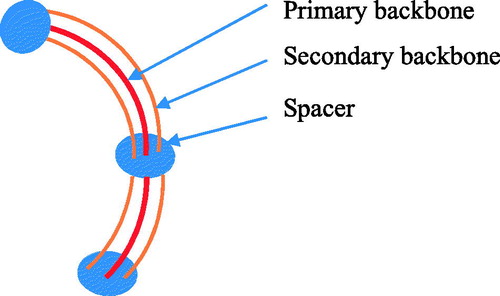
The steerable catheter with a multi-backbone was designed by eliminating the backlash, enhancing the down-scalability, and improving the payload. Such a steerable catheter is typically composed of several parallel elastic rods or tubes. For instance, shows a steerable catheter, which has a primary backbone and two secondary backbones; the two secondary backbones function to control the deflection. Xu and Simaan [Citation41] reported a single-section continuum robot for minimally invasive surgery. It has four super-elastic NiTi tubes as its backbones. One primary backbone is centrally located and is attached to the base disk and end disk. Three identical secondary backbones are equidistant from each other and serve as driven tendons. Each secondary backbone is actuated in push–pull mode by an actuation rod.
Figure 8. Schematic diagram of the structure of the multi-backbone steerable catheter.
2.1.2. Multi-section
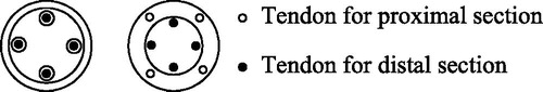
In order to provide a sufficient number of degrees of freedom (DOF) or a sufficient large workspace for tasks, the steerable catheter has been designed to have multiple sections (as each section serves as one link and the connection between two neighbouring links gives a more freedom of relative movement between the links). Each section is steered with a group of tendons. The number of tendons for the distal section may not be the same as the number of tendons for the proximal section. For the multi-section tendon-driven catheter, the way the sections are connected (or called the section coupling) is crucial to the dexterity and overall size of the catheter. Usually, there are two ways for the section coupling: co-placed and distributed (). In the co-placed coupling of sections, the tendons for the proximal section share the same pathways with the tendons for the distal section; the examples can be found in [Citation50,Citation51]. In the distributed coupling of sections, the tendons for each section have their independent pathways; the examples can be found in [Citation47,Citation52,Citation53]. The co-placed section coupling may render to a smaller diameter catheter while the distributed section coupling has more dexterity to comparing with the co-placed section coupling.
Figure 9. The section coupling (Left: co-placed; Right: distributed).
Camarillo et al. [Citation52] designed a catheter with two articulated sections and two tendons per section arranged antagonistically from the distal to proximal. The way the sections are coupled is the distributed one. Carlson and Barbagli [Citation47] presented a two-section catheter. Each section is controlled with four orthogonal tendons. The type of the section coupling is a distributed one. Xu and Simaan [Citation51] presented a three section multi-backbone continuum robot for minimally invasive surgery. The structure of each section is the same as their single section multi-backbone continuum robot [Citation41]. The type of the section coupling is a co-placed one. The backbones of the proximal and middle sections are concentric NiTi tubes, while the backbone of the distal section is the NiTi beam, which passes through the backbone tubes of the middle section.
Tendon-driven catheters have simple structures and can be steered remotely easily. Due to the actuation principle, the structure is relatively bulky, causing the limit in terms of the small size of catheters (in particular to the multi-section catheter). The friction between the tendon and guide channel as well as the backlash in the joints of the tendon makes it difficult to control the catheter.
2.2. Magnetic navigation catheters
In the magnetic navigation technique, the catheter with the magnetic distal tip is steered within the patient body. Several large magnets are placed on either side of the patient, which generates a magnetic field around the patient. Physicians can control the distribution of the magnetic field to deflect the distal tip of the catheter within the patient body to the desired direction.
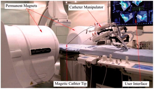
The commercially available products for magnetic navigation catheters include Niobe® ES magnetic navigation system (Stereotaxis, St. Louis, MO, USA) (Stereotaxis 2016) and Catheter Guidance, Control and Imaging-Maxwell (CGCI) (Magnetecs, Inglewood, CA, USA) (Magnetecs 2016). Niobe® ES magnetic navigation system is designed to make the treatment of complex cardiac arrhythmias safe and effective () (Stereotaxis 2016), [Citation54]. There are two permanent magnets to generate a uniform magnetic field (0.08 T) in this system. The distal tip of the catheter is embedded with a small permanent magnet that interacts with the magnetic field. The intensity of the magnetic field is controlled by adjusting the relative position of the two permanent magnets. The insertion or retraction of the catheter is controlled by a catheter manipulator. Operators steer the catheter fully automatically by a joystick or mouse based on the image feedbacks from a user interface system. The system proved a safe and effective tool in the treatment of supraventricular and ventricular arrhythmias based on the clinical feedbacks [Citation55–60], (Arya et al. 2008). The main advantages with the remote magnetic navigation are the reduced fluoroscopy time and less complication. The drawback is, however, the increased total procedural time.
Figure 10. Niobe® ES magnetic navigation system.
The magnetic field can also be generated by the electromagnets in addition to the one generated by the permenent magnets Nguyen et al. [Citation9,Citation61–63]. Stereotaxia Inc. designed a similar magnetic navigation system as Niobe® ES magnetic navigation system in the early stage named Telstar [Citation61], in which the magnetic field is generated by three orthogonal electromagnets. Directional catheter navigation is accomplished by generating a desired magnetic field vector. Nguyen et al. [Citation63] presented the CGCI system for cardiac surgery. The system consists of eight coil-core electromagnets, arranged semi-spherically around the chest on a standard fluoroscopy table. They can generate approximately 15 cm3 3 D region with a maximal uniform magnetic field strength of 0.14 T and the maximal perpendicular force (25 g) at the distal tip of catheter in the Niobe magnetic navigation system. The precision of the magnetic field both in its magnitude and direction is greatly improved, and the nearly real time control of the catheter tip can be achieved. Jeon and Jang [Citation9] developed a catheter system to steer and unclog the catheter by the magnetic torque and force. The catheter is composed of a flexible tube with a rotatable drill tip at the distal tip, which is a permanent magnet. The magnetic field is generated by two types of magnetic coils: uniform coils and gradient coils. The magnetic torque and force can be independently controlled. To compare with the magnetic fields generated by permanent magnets, they have two advantages: (1) they can increase the stability and contact force of the distal tip by increasing the strength of the magnetic fields; (2) The system can continuously and rapidly shape and reshape the magnetic fields, which provides instantaneously changes to the tip of the magnetized catheter, leading to a near real-time remote navigation.
Another way for magnetic navigation is to guide the catheter inside a magnetic resonance imaging (MRI) system. Gosselin et al. [Citation64] presented a catheter and a guidewire with the ferromagnetic heads, steered by applying magnetic gradients inside a MRI system. However, the two ferromagnetic spheres introduce undesired dipole-dipole interactions. Gudino et al. (Gudino et al. 2011) reported that a micro-catheter was steered inside a MRI system. The tip of the catheter was built by an array of steering coils. Similar studies can be found in [Citation65,Citation66]. Their work shows that the optimization of the catheter design as well as the coil activation current is necessary for the safe remote control of the navigation of the catheter [Citation65].
The control of the magnetic field with the permanent magnets by changing their relative position but without a power switching mechanism may cause some safety problem. Indeed, the switching of the entire system (on and off) can easily be realized by the electromagnets [Citation56,Citation61,Citation63]. The major drowback of the control with the electromagnets is that the magnets show a nonlinear behavior, especially hysteresis, which is a challenge to control. Yet, another drawback is that the control of horizontal bending and that of vertical bending are highly coupled. Finaly, only one section structure can be realized by the magnetic technique due to the limitation that the magnetic field always serves as one source of driving.
2.3. Soft material driven catheters
Soft material driven catheters are made by so-called smart materials, including shape memory alloy (SMA), hydraulic bellows, and conducting polymers, and they can be bent continuously via their own structures rather than via other external mechanisms (i.e., tendon and magnetic field). SMAs, especially of the nitinol family of material, have super-plasticity, biocompatible, high recoverable strains, good kink resistance, good steer-ability and torque-ability. SMAs can be made in a very small diameter (under 1 mm) and this feature makes them an ideal candidate for the guide-wires or catheters for MIS [Citation67,Citation68]. The catheters built with SMAs can be classified into two categories based on how the effect of SMA is applied to manipulate the tip: (1) the catheter is entirely shaped with the SMA effect, and (2) the tip of the catheter is shaped with the SMA effect.
2.3.1. Shape memory effect catheters
Catheters of this type are actuated with the SMA effect only. The catheter bends and shrinks due to the force generated by SMA actuators when heated. The SMAs transforms between the austenite phase and the martensite phase to generate force and deformation, induced by the temperature. After being plastically deformed in its low temperature (martensite) phase, the SMA material can recover strains up to 8% when heated to austenite (Tung et al. 2008). The structure of SMAs can be wires, coils, carved tubes, and flat springs.
Dario et al. [Citation14] designed a catheter tip actuated by four SMA wires (90° apart), which are further embedded into the wall of the catheter. Four optical fiber sensors are embedded in the wall in order to get feedback information. The SMA wires are heated and cooled by circulating fluid through the same lumens, in which the SMA wires are located. Takizawa et al. [Citation69] presented a catheter actuated by three SMA wires (120° apart) with 1.5 mm diameter. Tactile sensors are designed and installed on the tip of the catheter. It takes around 2 seconds to achieve the maximum bending angle 45°. Jayender et al. [Citation70,Citation71] developed an catheter actuated by three SMA wires spaced at 120°. The wires are micro-welded to stainless steel pads, which are further glued to the central catheter to be a multi-section catheter to obtain varying bending angles. The catheter with SMA wires is packaged in the case of injury of the vessel wall by the heat. Similar catheters for neuroradiology can be found in [Citation13,Citation72].
Using SMA wires can facilitate the miniaturization of the catheter. It can produce a large force but only generate a small displacement. In order to obtain a large displacement (which can subsequently produce a large bending angle) and quick response, micro SMA coils are used. The catheters are composed of multi-links which can produce an enough bending angle. Lim et al. [Citation31,Citation32] developed a multi-link active catheter with 2.8 mm diameter. It consists of several links and joints made of SMA actuators. Three SMA coils are located at nearly 120° apart and heated by electrical current. The SMA actuators can be heated directly. However, they have low resistance (10 Ω). They can produce an indirect heating method using a nickel thin film deposited on a parylene coated SMA actuator (200 Ω). The maximum bending angle is 13°. Haga et al. [Citation33,Citation34] presented three active catheters whose diameters are less than 2 mm, which are actuated by series of distributed SMA coils. The first catheter consists of many distributed link-joint units and the diameter is 1.2 mm. Three groups of SMA coils are fixed at equivalent angles between two links and one joint. When the SMA coils are heated with the electrical current above a certain transition temperature, it shrinks and bends the catheter. The maximum bending angle is 11° under 80 mA input current. The other two catheters eliminate the link-joint units and the SMA actuators are fixed on the inner tube with adhesive materials. One has the liner coil outside the SMA actuators, and the other has the liner coil inside the SMA actuators. The liner coil is used as an electrical common ground and both terminals of each joint are connected to this liner coil. Their bending angles can achieve 60° under 50 mA input current and 90° under 80 mA input current. They also designed a guide-wire with only 0.5 mm diameter [Citation73]. It can bend to one direction using a meandering SMA actuator with a stainless coil spring, and it can bends over 60° under 50 mA input current.
Although SMA actuators offer a compact alternative to conventional actuators, SMA actuators have several drawbacks: (1) they have relatively low machinability and need a special manufacturing process, i.e. laser machining; (2) the active catheters usually need several linked SMAs, and this requires many lead wires to control the SMA actuators, making the system more complex; (3) compared with the tendon-driven catheters and magnetic catheters, the SMA-catheter generates a relatively low tip-force; (4) the heat that is needed for the SMA actuators to work may cause some problem in terms of safety (e.g., removal of the heat generated from human body is a challenge). A high temperature may cause the injury of cells or tissue; (5) they have a nonlinear behavior of the strain with respect to the electric current or temperature. SMAs have a high hysteresis characteristic, as a result of which their control can be difficult [Citation70,Citation71].
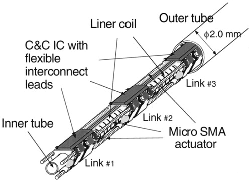
Efforts have been taken to overcome the shortcomings of the SMA-catheters. Regarding Problem (2), as mentioned above, Park and Esashi (Park and Esashi 1999) presented a multi-link active catheter with an integrated COMS interface circuit for communication and control (C&C IC) within a 2.0 mm diameter (). The number of lead wires is reduced to 3. Three SMA actuators are fixed between the links 120° apart with 3% deformation strain. The catheter bends due to SMA actuators. The maximum bending angle is 51° under 100 mA input current.
Figure 11. Overall structure of the catheter developed by Park and Esashi (Park and Esashi 1999). Reprinted with the permission from (Park and Esashi 1999) © 1999 IEEE.
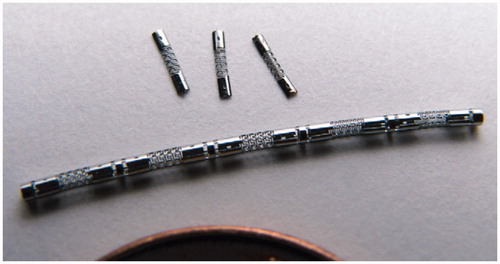
Regarding Problem (4), Tung et al. [Citation74], (Tung et al. 2008) developed an actuator made from the laser machined SMA tubes with 1.5 mm long and 1.27 mm diameter (). It can produce force of 1–2 N at 20% elongation. The 180° turn can be achieved with 9 actuators (each with bending angle of 20°).
Figure 12. Laser machined SMA actuators by Tung et al. (Tung et al. 2008). Reprinted with the permission from (Tung et al. 2008) © 2008 Elsevier.
2.3.2. Steerable catheters with a partial shape memory effect
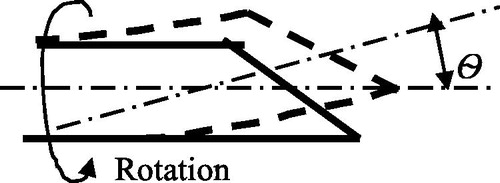
In this case, the super-elasticity and large strain recovery properties of SMA materials are exploited yet without any heating process. Such an actuation mechanism is usually applied to flexible needles that directly interact with soft tissues [Citation75,Citation76], (Webster 2007). Abolhassani et al. [Citation77] provided a survey regarding needle insertion into soft tissues. One way to steer such a kind of needle is to make the needle with a beveled tip and to steer it using the asymmetric forces on the beveled tip. The beveled tip of the flexible needles can be bent due to the asymmetry of the tip when the tip contacts the tissue during insertion. The beveled tip can be re-oriented by rotation and then subsequently pushed forward to the target (). The flexible needle will follow the insertion path when retracted. It is noted that the steerable needle cannot be operated in a free space but a constrained space.
Figure 13. Movement of the needle with a bevel tip tiedles.
Webster et al. [Citation75,Citation76] presented a flexible needle made from Nitinol for the insertion of steerable needles. The beveled steering effect is enhanced with the flexible material. A robot actuates and controls the needle. According to Webster et al. [Citation75,Citation76], the depth of needle in the tissue is 22–25 cm, the deflection of needle is about 10% of the depth, and the velocity of the needle ranges from 0.5 to 2.5 cm/s. In Webster et al. [Citation75,Citation76], a kinematic model was used for control, which is limited in the control performance due to missing the knowledge of the needle–tissue interaction along the length of the needle. Alterovitz et al. [Citation78,Citation79] developed a 2 D planning algorithm for the insertion of a flexible needle with a beveled tip into soft tissues with obstacles. The interaction between the needle and soft tissue was modeled with the finite element method, and the model was used for the planner to account for tissue deformation. Golzman and Shoham [Citation80] presented a robotic system for steering the flexible needles in soft tissue in the real-time closed-loop control. The planned needle-tip trajectory avoids the obstacle and hits the targets. Duindam et al. [Citation81] presented a constant-time 3 D motion planning algorithm for flexible needles using a so-called geometrical inverse kinematic model. Abayazid et al. [Citation82] presented an ultrasound image guided control system to steer a flexible needle made from nitinol with an asymmetric tip. They used both the kinematics model and kinetics model of the needle-tissue interaction to predict the needle deflection and to control the needle.
2.3.3. Concentric tubes
In another way to steer the catheter or needle, the concentric tubes (Webster 2007), [Citation83–85] are developed, which are made of a set of flexible tubes embedded with each other. When a curved elastic tube (guide-wire or catheter) is inserted into a series of elastic tubes, their shapes are decided by the mutually resultant curvatures because they have the same stiffness. By translation and rotation of the tubes with respect to each other, their curvatures and overall length of tubes may vary, so as to serve as the purpose of manipulation. The tubes are typically made from Nitinol in its super-elastic phase. They can be made into desired shapes by the heat treatment before assembly. A review of the state of arts of the device of the concentric tube robot can be found in [Citation86].
Specifically, Webster et al. (Webster 2007), [Citation85] presented an active cannula made from nitinol and composed of three telescoping, concentric and pre-curved tubes (). The diameter of the largest part of the tube is 2.4 mm and the diameter of the smallest part is 0.8 mm. Each tube has a translation and rotation degree of freedom. A unit with three tubes and six-DOFs controls the concentric tubes. Other important achievements regarding the design, modeling and control of the concentric tube system can be found in [Citation86–90].
Figure 14. Active cannula made of super-elastic Nitinol tubes [Citation85]. Reprinted with the permission from [Citation85] © 2009 IEEE.
![Figure 14. Active cannula made of super-elastic Nitinol tubes [Citation85]. Reprinted with the permission from [Citation85] © 2009 IEEE.](/cms/asset/759e802a-7e62-4072-b780-169c09c15c3d/icsu_a_1526972_f0014_c.jpg)
Dupont et al. [Citation83] developed a concentric tube robot, composed of three pre-curved nitinol tubes, which is similar to the active cannula by Webster et al. [Citation85]. The diameter of the largest part is 2.77 mm and the smallest part is 1.85 mm. A tele-operation system was developed to achieve the real-time position control of tubes based on the forward kinematics and inverse kinematics models. Gosline et al. [Citation84] used this concentric tube robot to percutaneously access the right atrium and deploy a tissue approximation device to complete the intracardiac beating-heart surgery. Other important achievements regarding design, modeling and control of the concentric tube system can be found in [Citation91–93]. Xu et al. [Citation94,Citation95] presented a concentric tube robot composed of two Nitinol tubes. The outer tube was fixed while the inner tube was rotated. The position of the distal tip can be obtained from an electromagnetic tracking system. A fast torsionally compliant kinematic model using the global variables and model based control method was developed to control the tubes.
Compared with other types of robotic catheters, the concentric tubes are more flexible and smaller in terms of diameters. They do not utilize the full shape memory effect (i.e., without the need of heating the material). Additional sections can be easily added by increasing the number of tubes, which is often a challenge with other types of steerable catheters. Furthermore, the lumen of the concentric tubes can provide addition tubes or control wires for the tools mounted at the distal tips. However, the comcentric tube steerable catheter has several limitations: (1) the selection of the initial curvature of each tube is non-trivial task (Webster 2007); (2) the small radii of the pre-curvature may cause the tube damage; (3) instability, caused by the snapping; (4) low rigidity to the environment; (5) difficulty in control for achieving a high steering accuracy; and (6) the bulkiness of control unit outside of partient.
2.3.4. Conducting polymers driven catheters
To a class of polymers, they can change shape after being doped electrochemically. Particularly, when ions are driven into such polymers axially, the polymers change their volumes axially, and when ions are driven into such polymers transversally, the polymers bend. Such a polymer is called electro-active polymer (EAP). Catheters can be driven by EAP. Particularly, the tip of catheters is made of EAPs and put in an electrolyte environment. After the eletrical current passes through the polymers, ions are driven into polymers to expend the polymers. Dops can be configured to make the tip bending. The advantage of the EAP tip of the catheter includes: (1) low voltate (under 2 V) and (2) ease with miniaturization [Citation96].
Guo et al. [Citation11] proposed three micro catheters with an active guide-wire that has two bending degrees of freedom, actuated by an Ionic Conducting Polymer Film (ICPF). The basic structure of the catheter is shown in . The bending principle is that an ICPF fixed at the distal tip of a guide-wire can be bent under a voltage input. Two lead wires were used for supplying the electric energy to the ICPF. The diameters of the micro catheters were 1 mm, 1.3 mm and 2 mm, respectively. The ICPF actuator had fast response, driven by low voltage (2 V), compared with the SMA in the wet condition without electrolysis and heat, safety in body [Citation97]. The maximum bending angle was 41° with the distal displacement of 10 mm. Della Santa et al. [Citation30] proposed two active catheters with 0.8 mm diameters with the polypyrrole conducting polymer and the ionic conductor solid polyelectrolyte as an ionic reservoir. In one catheter, two groups of conducting polymer actuators in the form of thin strips with a solid polymer electrolyte (SPE), respectively, are inserted in the catheter wall. In the other catheter, the wall of the catheter is made of conducting polymer fibers (CPF) embedded in a SPE elastromeric matrix (50% SPE and 50% CPF). The maximum bending angles (with a distal placement of 7.4 mm) are 28° and 24°, respectively. One drawback with SPE is that its stiffness is too low. Sewa et al. [Citation98] presented a gold chemically plated perfluorocarboxylic acid film for the catheter system. The polymer can be bent 90° with the 8 mm displacement of the distal tip under 2 V input voltage in water. The polymer also shows durability more than 10 million cycles. Alici et al. [Citation99] proposed a conducting polymer actuator, which has potential to be the bending of the tip of the steerable catheter. The electrolyte layer in the middle is the polyvinylidine fluoride, which is clamped by two polymer polypyrroles as the electroactive components. The thin layers of the platinum are coated onto the polypyrroles to increase the conductivity. The maximum bending angle for the actuator strip with the length of 10 mm, the width of 1 mm and the thickness of 0.21 mm can be over 90° under 1 V input voltage. However, the maximum output force at the tip is only 0.006 N under 1 V input voltage. Fang et al. [Citation100] developed an active guide-wire for cardiac catheterization by using the ionic polymer metal composites (IPMCs). A pair of parallel IPMCs are fixed at the distal tip of guide-wire, in particular, one serving as an actuator and the other serving as a sensor which uses the inverse way. The control signal consists of high and low frequencies. The low frequency signal makes the IPMC to deform and change its surface electrical resistance, while the high frequency signal retains the deformation information. By utilizing a lock-in amplifier to demodulate the high frequency signal, the deformation can be measured. The main drawback of the conducing polymers is of relatively low response and the nonlinearity due to their actuation principle, i.e. hysteresis and back relaxation. It is a challenge to control such a kind of actuators.
Figure 15. Basic structure of the micro catheter [Citation11]. Reprinted with the permission, from [Citation11] © 1995 IEEE.
![Figure 15. Basic structure of the micro catheter [Citation11]. Reprinted with the permission, from [Citation11] © 1995 IEEE.](/cms/asset/05247a7b-c3b0-4570-9f30-8fc1a889e16e/icsu_a_1526972_f0015_b.jpg)
2.3.5. Hydraulic pressure driven catheters
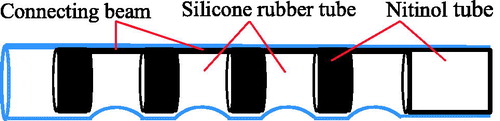
Another actuation principle is that the catheters are composed of one or several hydraulic bellows and the distal tips are steered by hydraulic pressure of bellows. The variation of hydraulic pressure inside the bellows modifies their lengths and, thus the bending of the catheter. Haga et al. (Haga et al. 2005) developed a catheter of 0.94 mm in diameter, actuated by the hydraulic suction mechanism for intravascular MIS. The catheter is made of the Nitinol tube covered by a silicone rubber tube (), in which the nitinol tube is cut of a line of rings with the connecting beams. The catheter is filled with water and its bending angle is controlled by the suction of water.
Figure 16. Structure of the catheter developed by Haga et al. (Haga et al. 2005). Reprinted with the permission from (Haga et al. 2005) © 2005 IEEE.
Bailly et al. [Citation10] proposed a two-section catheter called MALICA for the endovascular treatment of aortic aneurysm. The structure of catheter consists of two bases interconnected by three 120° positioned bellows. The actual prototype has a diameter of 4.9 mm, a length of 20 mm, and a working channel of 2 mm diameter and includes two spacer disks for each section (). The pressure variation inside the bellows leads to the variation in their length, which then induces the bending of the distal tip. The section structure is modular, which easily builds a multi-section catheter. Bailly et al. [Citation10] proposed another catheter, in which the distal tip of catheter is driven by three completely stress-free electrodeposited nickel bellows that are actuated by hydraulic pressure. To prevent bellows from buckling while maintaining a sufficient bending, two intermediate spacer disks are used. Ikeuchi and Ikuta [Citation101] presented a micro active catheter with 0.3 mm diameter using a membrane micro emboss following excimer laser ablation process. A bellow at the tip is composed of a series of folded micro-chambers connected by micro-channels. The bellow can be bent on one side by hydraulic pressure within 0° to 180°. Ikuta et al. [Citation8] proposed a two-section hydraulic pressure driven active catheter (). They use two valves with a different range of pressures to control the two sections sharing common bellows. Each section has a bellows-shaped bending actuator and a micro valve to control the opening and closing the channels respectively, in particular, a low-pass valve (LPV) and a high-pass valve (HPV). Each section can be bent when the bellows is expanded by the normal saline which is not harmful for the patients in the event of the leak.
Figure 17. The prototype of two-section catheter by Bailly et al. [Citation10]. Reprinted with the permission from [Citation10] © 2005 IEEE.
![Figure 17. The prototype of two-section catheter by Bailly et al. [Citation10]. Reprinted with the permission from [Citation10] © 2005 IEEE.](/cms/asset/a26ce06f-96c0-42a4-be79-498960d27299/icsu_a_1526972_f0017_c.jpg)
Figure 18. Hydraulic pressure driven active catheter [Citation8]. Reprinted with the permission from [Citation8] © 2012 IEEE.
![Figure 18. Hydraulic pressure driven active catheter [Citation8]. Reprinted with the permission from [Citation8] © 2012 IEEE.](/cms/asset/451f321a-dcf2-44da-a89b-eecb9217cb6b/icsu_a_1526972_f0018_c.jpg)
The catheter driven by hydraulic pressure is safer than other types of catheters and retreated quickly due to its actuation principle. Nevertheless, it shows some drawbacks. The output force is relatively small, which cannot complete some complex tasks. It needs bellows and micro-valves to control hydraulic pressure, which is bulky for catheters and needs relatively complex fabricating techniques. It may have the leakage problem and cause pressure losses (thus limit the efficiency of catheters).
2.4. Hybrid actuation catheters
Combination of any two actuation principles (Section 2.2 and Section 2.3, respectively) will result in a new multi-section catheter, called hybrid actuation catheter, which is promising to achieve a relative compact structure with easy control. Details of the engineering hybridization principle can be found in [Citation102,Citation103].
Butler et al. [Citation12] presented a robotic endoscopy for MIS, which is composed of a steerable concentric tube manipulator and an exoskeleton designed to manipulate a manual endoscope (). The system consists of five segments. Part A is the initial portion of the scope neck with the rigid torsion. Part B is the bending section which is controlled by tendons. Part C is a short, straight and rigid section, which houses the tip optics and the steerable concentric tube (Part D). The concentric tube can be rotated and translated with its stiffness dominated by the scope. Part E is a straight mono-polar cautery wire device with its stiffness dominated by the concentric tube.
Figure 19. Schematic diagram of robotic endoscopy developed by Butler et al. [Citation12]. Reprinted with the permission from [Citation12] © 2012 IEEE.
![Figure 19. Schematic diagram of robotic endoscopy developed by Butler et al. [Citation12]. Reprinted with the permission from [Citation12] © 2012 IEEE.](/cms/asset/fc0636a8-282a-402c-abdf-5a7051bd091c/icsu_a_1526972_f0019_b.jpg)
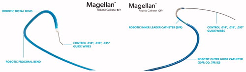
The MagellanTM robotic catheters, designed and manufactured by Hansen Medical Inc. [Citation7], have three sections for the peripheral vascular intervention (). MagellanTM robotic catheters have three different sizes (6 Fr, 9 Fr and 10 Fr), depending on the different diameters of the proximal part of the catheters. The middle section and proximal section are driven by a group of tendons, and the distal section is a pre-curved nitinol guide wire. The distal tip can be rotated and pre-curved by the middle section. By comparing with the robotic endoscopy by Butler et al. [Citation12], the maneuverability of the MagellanTM robotic catheters is improved by incorporating the tendon-driven section into the pre-curved system. Chikhaoui et al. [Citation104] proposed a steerable catheter by combining a concentric tube system and a micro-soft actuator, and the micro-soft actuator is still under development.
Figure 20. Magellan™ Robotic Catheter. (Left: Magellan™ 6 Fr Robotic Catheter, available at: http://www.hansenmedical.com/us/ en/ vascular/magellan-robotic-catheters/magellan-10fr-robotic-catheter; Right: Magellan™ 10 Fr Robotic Catheter, available at: http://www.hansenmedical.com/us/en/ vascular/magellan-robotic-catheters/magellan-10fr-robotic-catheter).
3. Discussion
Each type of steerable catheters has advantages and disadvantages. A comparison of different types of steerable catheters will be discussed in this section from the aspects of maneuverability, performance, size of catheter, safety, and cost in particular.
3.1. Manoeuvrability and performance
Manoeuvrability includes navigation and capability of being used for complex tasks. Navigation refers to the control of bending angle. The easier and faster to control the bending angle with a large amplitude, the better maneuverability. Catheters driven by tendons or hydraulic pressure can easily control the bending angle (the bending angle up to 180° can be achieved). The friction between the tendons and pathway, along with the backlash and slack of the tendons, can cause some difficulty in control of the tip of the tendon-driven catheter in terms of high accuracy. The magnetic catheter can achieve a large bending angle. The catheter driven by SMA actuators or by the conducting polymer can only achieve a relatively small bending angle compared with the foregoing three types of catheters. The maneuverability of pre-curved nitinol catheters is relatively poor, as catheters are not articulated in terms of their structure. Such a catheter usually needs to work in a semi-automatical manner (i.e., works with the human operator) – see the work of Couture and Szewczyk [Citation72]. This semi-automated system concept is a basic reason that such catheters are ususally simple in their structure and easy for manufacturing. For the capability that a catheter can be used for performing complex tasks, there are the following factors: the output force, accuracy of maneuver, DOF and workspace of catheters. If the output force is large and accurate with a sufficient number of DOFs and a sufficiently large workspace, the catheter can perform complex tasks. The tendon-driven catheters have a fast maneuver speed in comparison with the other types of catheters, and they can also generate a large force. The response of the magnetic navigation catheter system cannot reach too fast when the magnetic field is generated by permanent magnets. A delay occurs between designation of the magnetic field vector and catheter movement [Citation61,Citation63]. The hysteresis should be taken into account in control of this kind of catheters. The output force can be controlled by the strength of the magnetic field. The catheter driven by hydraulic pressure and a pre-curved nitinol catheter are inherently more compliant, which restricts their output force and stability. Catheters actuated by SMAs and conducting polymers rely on their materials. These materials show significant nonlinearities (i.e. hysteresis and time-varying mechanical characteristics), which is challenging to the control of such catheters. Accuracy of the maneuver is low with SMAs but the output force is high and the maneuver range is large. Catheters actuated by the conducting polymers have a fast response.
The DOFs and workspace are two basic requirements for the catheters. The magnetic catheters have a limited workspace and DOF due to the single-section structure. There is an approach to combining several catheters in operation to increase the DOFs and workspace. For instance, Simaan et al. [Citation50] proposed a three-armed robot with three distal dexterity units (DDUs), which serve as three tendon-driven steerable catheters for MIS of the throat, in particular two for manipulation and one for suction. In the magnetic navigation catheter system, two or more catheters cannot be steered in the magnetic field simultaneously, because two or more catheter tips interfere with each other by the magnetic fields. However, the other types of catheters can avoid this problem.
3.2. Size of the catheter
For the MIS surgery, the small diameter of the catheter is one of the basic requirements. The size depends on the structure and fabricating process of catheters. The tendon-driven catheter has one or several tendons, which transmit the input force to the distal tip. The tendons must have a sufficient stiffness to overcome the friction between the tendons and channels. They cannot be made in very small diameters in terms of reliability. This drawback may be amplified with more numbers of sections. Although the hydraulic pressure driven catheters have one or several hydraulic bellows, the catheters can be made into very small ones. They can be made with multi-sections without increasing the hydraulic bellows by using different pressure valves. The steerable catheters driven by SMAs, conducting polymers share some common features, that is, the actuators are fixed at the distal tip and thin lead wires are used for motion and force transfer. The COMS interface circuit can reduce the lead wires. This kind of catheters can be made in very small size. The magnetic catheter embeds a small magnetic tip at the distal tip only. They do not contain any other wires or channels, which makes them with small diameters. The pre-curved flexible nitinol catheter is the same as the conventional catheter or micro-catheter in terms of the structure. So that, concentric tubes can be fabricated and assembled into very small diameters.
3.3. Safety
Safety is one of the important factors for medical devices. A catheter must be maneuvered without causing any complications, such as perforation. One factor that affects the safety is the stiffness of catheters. The tendon-driven catheters and SMA catheters are relatively rigid, and therefore they have a potential risk of perforation. To avoid this, the accurate information of forces between the catheter and tissues has to be available to the human operators or robots during the operation. Various force sensors are developed and installed at the distal tips of catheters. However, the force sensor is not as reliable as the haptic feeling of physicians. Magnetic navigation catheters and conducting polymers catheters can be made by very soft and small in sizes with yet relatively rigid distal tips. These catheters as well as hydraulic pressure catheters are inherently more compliant, and they are unlikely to cause perforation. It is worth to mention that some clinic feedbacks [Citation54,Citation59] have shown that the magnetic navigation catheter systems (Niobe systems in particular) were conducive to reducing the complication. However, from other clinic feedbacks [Citation2], the complications are not reduced with the Sensei X Robotic Catheter System, and the complications are even higher than manual operations. This phenomenon may be related to a relatively high rigidity of this kind of catheters.
The catheters actuated by shape memory effects which are further driven by electrical power need some attention to safety, as they may cause the overheat problem. As opposed to such type of catheters, catheters driven by conducting polymers with small voltage (under 1V) are much safer. The fluid in the hydraulic pressure catheters is usually a kind of physiological saline, which is not harmful to patients. The magnetic navigation catheter system needs more attention, as movement of the permanent magnet may hit patients or physicians.
3.4. Cost
The cost of medical devices is an essential concern both for physicians and patients. Among all the steerable catheter systems, the most expensive one is the magnetic navigation catheter system. The cost includes the cost for both the robotic system and the operation environment. Installing a magnetic navigation catheter system may require that the catheter system be equipped with steel plates and specialized equipment to prevent the magnetic fields from interfering with other equipment. Such installations can be costly and time consuming. Other types of catheters do not have special operation environment requirements, compatible and portable to the existing operation rooms. The catheters actuated by shape memory effects, conducting polymers and hydraulic pressure require relatively complex fabrication techniques and thus may increase the cost. The tendon-driven catheters and pre-curved SMAs are inexpensive compared with the others.
4. Conclusions and future research challenges
This paper presented a review of steerable catheters in the past decade. The paper takes a view that the steerable catheter is a human-machine system, and the machine system consists of the actuator, mechanism, and end-effector, called the generalized mechanism [Citation18]. Then, the classification of this generalized mechanism in the tissue environment was made based on the working principle of the mechanism. Specifically, the steerable catheter was classified into the following categories: (1) tendon driven, (2) magnetic field driven, (3) soft material driven, and (4) hybrid driven. To each of these categories, sub-categories were classified upon more specialized working principles. The classification of steerable catheters based on the tissue environment was also performed, specifically resulting in three categories: (i) the catheter (or flexible needle) is directly steered into the tissue, and (ii) the catheter is steered into channels in human body. After that, the classification along with discussion on the categories of steerable catheters was made upon the attributes such as: (a) navigation capability (or manipulability) and performance, (b) size (including the potential for miniaturization), (c) safety, and (d) cost.
There are several new findings generated from this review regarding the state of arts of steerable catheters along with identificaitn of the future challenges. First, there have been many steerable catheters developed; however, there seems to be no comprehensive evaluation system available in the literature. This situation can hinder the further advancement of the steerable catheter technology. A future effort is warranted on overcoming this shortcoming. The authors of this paper believe that a classification scheme based on function-behavior-structure (FBS) knowledge architecture [Citation24,Citation105] should be taken in future. A successful example of the classifiiction of systems based on the FBS knowledge architecture can be found on pipe inspection robots (Li et al. 2015) and stick-skip actuator system [Citation106]. Second, from the literature, there is little attention to the navigation of steerable catheters in various parts of human body. A misconception may occur such that steerable catheters are a fully automated system. In fact, the surgeon plays an important role in steering catheters. The entire system should be viewed as a human-machine (surgeon-catheter) system [Citation19]. It is worth to mention that a promising work of Couture and Szewczyk [Citation72] is in fact a human-device system – the rotation of the cathter requires a manual operation. Neverthelss, the operability of steerable catheters, collaborated the human physciain, is not discussed in literature, which warrants a future work. Third, the control of steerable catheters, especially the control of the tip force, has less been discussed; for instance, the issue of how to get the information of the tip force is not well discussed. It may be true that this issue can be addressed by designing a sensor on the tip; however, such a steerable catheter may not be very reliable, apart from the difficulty of installing a small sensor on the tip. A future effort should be taken on the topic of the tip force control. Fourth, the design of steerable catheters in literature is not quite systematic and rational from the point of view of engineering design excellence (Fan et al. 2015); [Citation102]. General design theories and methodologies in the engineering design community may further improve the design of the steerable catheter. A systematic and rational design process starts with the specificaiotn of design goals or functional requirements and constraints, namely in the case of the steerale catheter: (1) the size, (2) the workspace, (3) maneuverability and (4) stability. These goals may conflict with each other; in other words, the design of steerable catheters is a trade-off process. Further, each human individual is different, the steerable device may be desired to be patient-personalized. How to optimize such a trade-off process and to design adaptive catheters warrant some future attention. Design theories such as Axiomatic Design Theory (ADT) may need to be employed for the optimization of the design process, and the latest discussion of ADT is referred to (Fan et al. 2015). Finally, there seems to lack an effective analysis tool for simulating the dynamic behaviour of the steerable catheter, which is needed to optimize the design as well as to facilitate the development of an analytical model for the dynamic behaviour of the steerable catheter for the real time feedback control of the catheter. The previous studies in robotics, e.g., Bi et al. [Citation107], Zhang et al. [Citation108,Citation109], can certainly be extendable to the steerable catheter.
Funding
The supports to the present study from the China Scholarship Council (CSC) and the Fundamental Research Grant of National Natural Science Foundation of China (Funding No.: 51375166) are acknowledged.
Disclosure statement
No potential conflict of interest was reported by the authors.
References
- Aagaard P, Natale A, Di Biase L. Robotic navigation for catheter ablation: benefits and challenges. Expert Rev Med Dev. 2015;12:457–469.
- Di Biase L, Wang YAN, Horton R, et al. Ablation of atrial fibrillation utilizing robotic catheter navigation in comparison to manual navigation and ablation: single‐center experience. J Cardiovasc Electrophysiology. 2009;20:1328–1335.
- Miyazaki S, Nault I, Haissaguerre M, et al. Atrial fibrillation ablation by aortic retrograde approach using a magnetic navigation system. J Cardiovas Electrophysiol. 2010;21:455–457.
- Ullah W, Hunter RJ, Haldar S, et al. Comparison of robotic and manual persistent AF ablation using catheter contact force sensing: an international multicenter registry study. Pacing Clin Electrophysiol. 2014;37:1427–1435.
- Boston Scientific Inc. 2016. Electrophysiology Products, Corporate Overview. Available from: https://www.bostonscientific.com/content/dam/bostonscientific/Rhythm%20Management/general/Presentation%20Resources/EP-222901-AA_BSC_EP_Corporate_Overview-FINAL%20(2).pdf.
- Hansen Medical Inc. [Internet]; 2016a. Artisan® Extend Control Catheter. Available at: http://www.hansenmedical.com/us/en/cardiac-arrhythmia/artisan-extend catheter/product-overview.
- Hansen Medical Inc. [Internet]; 2016b. MagellanTM Robotic System. Available at: http://www.hansenmedical.com/us/en/vascular/magellan-robotic-system/product-overview.
- Ikuta K, Matsuda M, Yajima D, et al. Pressure pulse drive: a control method for the precise bending of hydraulic active catheters. mechatronics. IEEE/ASME Trans Mechatron. 2012;17:876–883.
- Jeon SM, Jang GH. Precise steering and unclogging motions of a catheter with a rotary magnetic drill tip actuated by a magnetic navigation system. Ieee Trans Magn. 2012;48:4062–4065.
- Bailly Y, Amirat Y, Fried G. Modeling and control of a continuum style microrobot for endovascular surgery. IEEE Trans Robot. 2011;27:1024–1030.
- Guo SX, Fukuda T, Kosuge K, et al. 1995. Micro catheter system with active guide wire. 1995 IEEE International Conference on Robotics and Automation, Vol. 1, pp. 79–84.
- Butler EJ, Hammond-Oakley R, Chawarski S, et al. 2012. Robotic neuro-emdoscope with concentric tube augmentation. 2012 IEEE/RSJ International Conference on Intelligent Robots and Systems (IROS), pp. 2941–2946.
- Szewczyk J, Marchandise E, Flaud P, et al. Active catheters for neuroradiology. J Robot Mechatron. 2011;23:105.
- Dario P, Valleggi R, Pardini M, et al. A miniature device for medical intracavitary intervention. In Micro Electro Mechanical Systems 1991;1991:MEMS'91. Proceedings. An Investigation of Micro Structures, Sensors, Actuators, Machines and Robots. IEEE, pp. 171–175.
- Kutzer MDM, Segreti SM, Brown CY, et al. 2011. Design of a new cable-driven manipulator with a large open lumen: Preliminary applications in the minimally-invasive removal of osteolysis. 2011 IEEE International Conference on Robotics and Automation (ICRA), pp. 2913–2920.
- Harada K, Bo Z, Enosawa S, et al. 2007. Bending laser manipulator for intrauterine surgery and viscoelastic model of fetal rat tissue. 2007 IEEE International Conference on Robotics and Automation, pp. 611–616.
- Zhang B, Kobayashi Y, Chiba T, et al. 2009. Robotic patch-stabilizer using wire driven mechanism for minimally invasive fetal surgery. 2009 Annual International Conference of the IEEE, Engineering in Medicine and Biology Society, pp. 5076–5079.
- Zhang WJ. 1994. An Integrated Environment for CADCAM of Mechanical Systems, Ph.D. thesis, printed by Delft University of Technology, The Netherlands, ISBN 90-370-0113-0, pp. 1–263.
- Cheng WB, Di YY, Zhang EM, et al. Modeling and in vitro experimental validation for kinetics of the colonoscope in colonoscopy. Ann Biomed Eng. 2013;1:1–10.
- Cheng WB, Moser M, Kanagaratnam S, et al. Overview of upcoming advances in colonoscopy. Dig Endoscopy. 2012;24:1–6.
- Cao L, Dolovich A, Zhang WJ. Topology optimization of efficient and strong hybrid compliant mechanisms using a mixed mesh of beams and flexure hinges with strength control. Mech Machine Theory. 2018;137:122301–122310.
- Cao L, Dolovich AT, Zhang WJ. Hybrid compliant mechanism design using a super flexure hinge element through a topology optimization technique. J Mech Des. 2015;137:092303–092310.
- Cao L, Dolovich AT, Schwab AL, et al. Towards a unified design approach for both compliant mechanisms and rigid-body mechanisms: module optimization. J Mech Des. 2015;137:122301–122310.
- Zhang WJ, Lin Y, Niraj S. 2005. On the Function-Behavior-Structure Model for Design. The 2nd CDEN Conference, Alberta, Canada, July 18-20. CD ROM, 8 pages.
- Robinson G, Davies JBC. 1999. Continuum robots-a state of the art. In Robotics and Automation, 1999. Proceedings. 1999 IEEE International Conference on Vol. 4, pp. 2849–2854.
- Walker ID. Continuous backbone “continuum” robot manipulators. ISRN Robotics. 2013;2013:1–19.
- Webster RJ, Jones BA. Design and kinematic modeling of constant curvature continuum robots: a review. Int J Robotics Res. 2010;29:1661–1683.
- Tiba A, Culbertson BM. Thermal, mechanical, and biocompatibility properties of cured multi-methacrylates derived from propoxylated, enzyme oligomerized BPA neat resins. J Macromol Sci Part A. 1999;36:1209–1226.
- Ali A, Plettenburg DH, Breedveld P. Steerable catheters in cardiology: classifying steerability and assessing future challenges. IEEE Trans Biomed Eng. 2016;63:679–693.
- Della Santa A, Mazzoldi A, De Rossi D. Steerable microcatheters actuated by embedded conducting polymer structures. J Intelligent Mat Sys Struct. 1996;7:292–300.
- Lim G, Minami K, Sugihara M, et al. 1995. Active catheter with multi-link structure based on silicon micromachining. 1995 IEEE Proceedings on Micro Electro Mechanical Systems, pp. 116–121.
- Lim G, Park K, Sugihara M, et al. Future of active catheters. Sens Actuators A Phys. 1996;56:113–121.
- Haga Y, Esashi M, Maeda S. 2000. Bending, torsional and extending active catheter assembled using electroplating. In Micro Electro Mechanical Systems, 2000. MEMS 2000. The Thirteenth Annual International Conference on, IEEE, pp. 181–186.
- Haga Y, Tanahashi Y, Esashi M. 1998. Small diameter active catheter using shape memory alloy. Micro Electro Mechanical Systems, 1998. MEMS 98. Proceedings., The Eleventh Annual International Workshop on, IEEE, pp. 419–424.
- Khoshnam M, Azizian M, Patel RV. 2012. Modeling of a steerable catheter based on beam theory. In Robotics and Automation (ICRA), 2012 IEEE International Conference on, pp. 4681–4686.
- Khoshnam M, Skanes AC, Patel RV. Modeling and estimation of tip contact force for steerable ablation catheters. IEEE Trans Biomed Eng. 2015;62:1404–1415.
- Guo X, Tegg TT, Stehr RE. 2011. Deflectable catheter with distal deflectable segment. U.S. Patent No. 7,985,215. Washington (DC): U.S. Patent and Trademark Office.
- Ganji Y, Janabi-Sharifi F. Catheter kinematics for intracardiac navigation. IEEE Trans Biomed Eng. 2009;56:621–632.
- Watson JR. 2013. Asymmetric dual directional steerable catheter sheath. U.S. Patent No. 8,500,733. Washington, DC: U.S. Patent and Trademark Office.
- Degani A, Choset H, Wolf A, et al. Percutaneous intrapericardial interventions using a highly articulated robotic probe. The First IEEE/RAS-EMBS International Conference on Biomedical Robotics and Biomechatronics 2006;7–12.
- Xu K, Simaan N. An investigation of the intrinsic force sensing capabilities of continuum robots. IEEE Trans Robot. 2008;24:576–587.
- Jung J, Penning RS, Ferrier NJ, et al. 2011. A modeling approach for continuum robotic manipulators: effects of nonlinear internal device friction. In Intelligent Robots and Systems (IROS), 2011 IEEE/RSJ International Conference on, pp. 5139–5146.
- Camarillo DB. 2008a. Mechanics and control of tendon driven continuum manipulators. PhD Thesis, Stanford University.
- Zhang B, Moser M, Zhang E, et al. Radiofrequency ablation technique in the treatment of liver tumours: review and future issues. J Med Eng Technol. 2013;37:150–159.
- Zhang B, Moser MAJ, Zhang EM, et al. A review of radiofrequency ablation: Large target tissue necrosis and mathematical modelling. Physica Medica. 2016;32:961–971.
- Murphy RJ, Moses MS, Kutzer MD, et al. 2013. Constrained workspace generation for snake-like manipulators with applications to minimally invasive surgery. 2013 IEEE International Conference on Robotics and Automation (ICRA), pp. 5341–5347.
- Carlson CR, Barbagli F. 2013. Robotic catheter systems and methods. U.S. Patent No. 8,391,957.
- Kanagaratnam P, Koa-Wing M, Wallace DT, et al. Experience of robotic catheter ablation in humans using a novel remotely steerable catheter sheath. J Interv Card Electrophysiol. 2008;21:19–26.
- Camarillo DB, Milne CF, Carlson CR, et al. Mechanics modeling of tendon-driven continuum manipulators. IEEE Trans Robot. 2008b;24:1262–1273.
- Simaan N, Xu K, Wei W, et al. Design and integration of a telerobotic system for minimally invasive surgery of the throat. The Int J Robotics Res. 2009;28:1134–1153.
- Xu K, Simaan N. Intrinsic wrench estimation and its performance index for multisegment continuum robots. Robotics. IEEE Trans. 2010;26:555–561.
- Camarillo DB, Carlson CR, Salisbury JK. Configuration tracking for continuum manipulators with coupled tendon drive. IEEE Trans Robot. 2009;25:798–808.
- Carroll S, Santoianni D, Thibault B, et al. 2011. Defined deflection structure. U.S. Patent No. 7,955,298. Washington (DC): U.S. Patent and Trademark Office.
- Ernst S, Ouyang F, Linder C, et al. Initial experience with remote catheter ablation using a novel magnetic navigation system magnetic remote catheter ablation. Circulation. 2004;109:1472–1475.
- Chun KJ, Wissner E, Koektuerk B, et al. Remote-controlled magnetic pulmonary vein isolation using a new irrigated-tip catheter in patients with atrial fibrillation. Circulation Arrhythmia Electrophysiology. 2010;3:458–464.
- Erni S, Schürle S, Fakhraee A, et al. Comparison, optimization, and limitations of magnetic manipulation systems. J Micro-Bio Robotics. 2013;1:14.
- Kim AM, Turakhia M, Lu J, et al. Impact of remote magnetic catheter navigation on ablation fluoroscopy and procedure time. Pacing Clin Electrophysiol. 2008;31:1399–1404.
- Pappone C, Vicedomini G, Manguso F, et al. Robotic magnetic navigation for atrial fibrillation ablation. J Am College Cardiol. 2006;47:1390–1400.
- Proietti R, Pecoraro V, Di Biase L, et al. 2013. Remote magnetic with open-irrigated catheter vs. manual navigation for ablation of atrial fibrillation: a systematic review and meta-analysis. Europace.
- Wood MA, Orlov M, Ramaswamy K, et al. Remote magnetic versus manual catheter navigation for ablation of supraventricular tachycardias: a randomized, multicenter trial. Pacing Clin Electrophysiol. 2008;31:1313–1321.
- Faddis MN, Blume W, Finney J, et al. Novel, magnetically guided catheter for endocardial mapping and radiofrequency catheter ablation. Circulation. 2002;106:2980–2985.
- Govari A, Altmann AC, Ephrath Y, et al. 2011. ROBOTIC DRIVE FOR CATHETER. U.S. Patent No. 20,110,040,150.
- Nguyen BL, Merino JL, Gang ES. Remote navigation for ablation procedures–A new step forward in the treatment of cardiac arrhythmias. Eur Cardiol. 2010;6:50–56.
- Gosselin FP, Lalande V, Martel S. Characterization of the deflections of a catheter steered using a magnetic resonance imaging system. Med Phys. 2011;38:4994–5002.
- Hetts SW, Saeed M, Martin AJ, et al. Endovascular catheter for magnetic navigation under MR imaging guidance: evaluation of safety in vivo at 1.5 T. Ajnr Am J Neuroradiol. 2013;34:2083–2091.
- Liu T, Cavusoglu MC. 2014. Three dimensional modeling of an MRI actuated steerable catheter system. In Robotics and Automation (ICRA), 2014 IEEE International Conference on, pp. 4393–4398.
- Duerig TW, Pelton A, Stöckel D. An overview of nitinol medical applications. Mat Sci Eng A. 1999;273–275:149–160.
- Morgan NB. Medical shape memory alloy applications - the market and its products. Mat Sci Eng A. 2004;378:16–23.
- Takizawa H, Tosaka H, Ohta R, et al. 1999. Development of a microfine active bending catheter equipped with MIF tactile sensors. In Micro Electro Mechanical Systems, 1999. MEMS'99. Twelfth IEEE International Conference on, pp. 412–417.
- Jayender J, Azizian M, Patel RV. Autonomous image-guided robot-assisted active catheter insertion. Ieee Trans Robot. 2008;24:858–871.
- Jayender J, Patel RV, Nikumb S. Robot-assisted active catheter insertion: algorithms and experiments. Int J Robotics Res. 2009;28:1101–1117.
- Couture T, Szewczyk J. Design and experimental validation of an active catheter for endovascular navigation. J Med Dev. 2017;12:011003–011022.
- Haga Y, Mineta T, Esashi M. 2002. Active catheter, active guide wire and related sensor systems. In Automation Congress, 2002 Proceedings of the 5th Biannual World, IEEE, Vol. 14, pp. 291–296.
- Tung AT, Park BH, Niemeyer G, et al. Laser-machined shape memory alloy actuators for active catheters. IEEE/Asme Trans Mechatron. 2007;12:439–446.
- Webster RJ, Kim JS, Cowan NJ, et al. Nonholonomic modeling of needle steering. Int J Robotics Res. 2006;25:509–525.
- Webster RJ, Memisevic J, Okamura AM. 2005. Design considerations for robotic needle steering. Proceedings of the 2005 IEEE International Conference on Robotics and Automation, pp. 3588–3594.
- Abolhassani N, Patel R, Moallem M. Needle insertion into soft tissue: a survey. Med Eng Phys. 2007;29:413–431.
- Alterovitz R, Branicky M, Goldberg K. Motion planning under uncertainty for image-guided medical needle steering. Int J Robot Res. 2008;27:1361–1374.
- Alterovitz R, Goldberg K, Okamura A. 2005. Planning for steerable bevel-tip needle insertion through 2D soft tissue with obstacles. Proceedings of the 2005 IEEE International Conference on Robotics and Automation, pp. 1640–1645.
- Glozman D, Shoham M. Image-guided robotic flexible needle steering. IEEE Trans Robot. 2007;23:459–467.
- Duindam V, Xu J, Alterovitz R, et al. Three-dimensional motion planning algorithms for steerable needles using inverse kinematics. Int J Robotics Res. 2010;29:789–800.
- Abayazid M, Roesthuis RJ, Reilink R, et al. Integrating deflection models and image feedback for real-time flexible needle steering. IEEE Trans Robot. 2013;29:542–553.
- Dupont PE, Lock J, Itkowitz B, et al. Design and control of concentric-tube robots. IEEE Trans Robot. 2010;26:209–225.
- Gosline AH, Vasilyev NV, Butler EJ, et al. Percutaneous intracardiac beating-heart surgery using metal MEMS tissue approximation tools. Int J Robotics Res. 2012;31:1081–1093.
- Webster RJ, Romano JM, Cowan NJ. Mechanics of precurved-tube continuum robots. IEEE Trans Robot. 2009;25:67–78.
- Gilbert HB, Rucker DC, Webster III, RJ. 2013. Concentric tube robots: The state of the art and future directions. In Int Symp Robot Res, 1–16.
- Burgner J, Rucker DC, Gilbert HB, et al. A telerobotic system for transnasal surgery. IEEE/ASME Trans Mechatron. 2014;19:996–1006.
- Rucker DC, Jones BA, Webster RJ. A geometrically exact model for externally loaded concentric-tube continuum robots. IEEE Trans Robot. 2010;26:769–780.
- Rucker DC, Webster RJ. Parsimonious evaluation of concentric-tube continuum robot equilibrium conformation. IEEE Trans Biomed Eng. 2009;56:2308–2311.
- Rucker DC, Webster RJ, Chirikjian GS, et al. Equilibrium conformations of concentric-tube continuum robots. Int J Robotics Res. 2010.
- Arabagi V, Gosline A, Wood RJ, et al. 2013. Simultaneous soft sensing of tissue contact angle and force for millimeter-scale medical robots. In Robotics and Automation (ICRA), 2013 IEEE International Conference on, pp. 4396–4402.
- Bedell C, Lock J, Gosline A, et al. 2011, May. Design optimization of concentric tube robots based on task and anatomical constraints. In Robotics and Automation (ICRA), 2011 IEEE International Conference on, pp. 398–403.
- Mahvash M, Dupont PE. Stiffness control of surgical continuum manipulators. Robotics, IEEE Trans. 2011;27(2):334–345.
- Xu R, Asadian A, Naidu AS, et al. Position control of concentric-tube continuum robots using a modified Jacobian-based approach. 2013 IEEE International Conference on Robotics and Automation (ICRA) 2013;5813–5818.
- Xu R, Patel RV. 2012. A fast torsionally compliant kinematic model of concentric-tube robots. In Engineering in Medicine and Biology Society (EMBC), 2012 Annual International Conference of the IEEE, pp. 904–907.
- Smela E. Conjugated polymer actuators for biomedical applications. Adv Mater. 2003;15:481–494.
- Oguro K, Asaka K, Takenaka H. 1993. Polymer film actuator driven by a low voltage. In Proceedings of 4th International Symposium on Micro Machine and Human Science (pp. 39–40).
- Sewa S, Onishi K, Asaka K, et al. 1998. Polymer actuator driven by ion current at low voltage, applied to catheter system. In Micro Electro Mechanical Systems, 1998. MEMS 98. Proceedings., The Eleventh Annual International Workshop on, pp. 148–153.
- Alici G, Mui B, Cook C. Bending modeling and its experimental verification for conducting polymer actuators dedicated to manipulation applications. Sensors Actuat A Phys. 2006;126:396–404.
- Fang BK, Ju MS, Lin CCK. 2009. Development of Active Guide-wire for Cardiac Catheterization by Using Ionic Polymer-Metal Composites. In 13th International Conference on Biomedical Engineering, Springer Berlin Heidelberg, pp. 340–343.
- Ikeuchi M, Ikuta K. 2009. Development of pressure-driven micro active catheter using membrane micro emboss following excimer laser ablation (MeME-X) process. 2009 IEEE International Conference on Robotics and Automation (ICRA'09), pp. 4469–4472.
- Cheng L, Lin Y, Hou ZG, et al. Adaptive tracking control of hybrid machines: a closed-chain five-bar mechanism Case. IEEE/ASME Trans Mechatron. 2011;16:1155–1163.
- Zhang WJ, Ouyang PR, Sun ZH. 2010. A novel hybridization design principle for intelligent mechatronics systems. In Proceedings of international conference on advanced mechatronics (ICAM2010), pp. 4–6.
- Chikhaoui MT, Rabenorosoa K, Andreff N. Kinematics and performance analysis of a novel concentric tube robotic structure with embedded soft micro-actuation. Mech Machine Theory. 2016;104:234–254.
- Zhang WJ, Wang JW. Design theory and methodology for enterprise systems (Editorial). Enterprise Inf Sys. 2016;10:245–248.
- Zhang ZM, An Q, Li JW, et al. Piezoelectric friction-inertia actuator - a critical review and future perspective. Int J Adv Manuf Technol. 2012;62:669–685.
- Bi ZM, Zhang WJ, Chen IM, et al. Automated geneartion of the D–H parameters for configuration design of modular manipulators. Robotics Comput-Integ Manufac. 2007;23:553–562.
- Zhang WJ, van der Werff K. Automatic communication from a neutral object model of mechanism to mechanism analysis programs based on a finite element approach in a software environment for CADCAM of mechanisms. Finite Elements Analysis Design. 1998;28:209–239.
- Zhang T, Backstrom K, Prince R, et al. 2014. Robotic dynamic sculpture. IEEE Robotics and Automation Magazine. September. 96–104. Digital Object Identifier
- Antman SS. Nonlinear problems of elasticity. New York: Springer Verlag; 1995.
- Bathe KJ. Finite element procedures. New Jersey: Prentice Hall; 1996.
- Bismuth J, Kashef E, Cheshire N, et al. Feasibility and safety of remote endovascular catheter navigation in a porcine model. J Endovascular Therapy. 2011;18:243–249.
- Bismuth J, Duran C, Stankovic M, et al. A first-in-man study of the role of flexible robotics in overcoming navigation challenges in the iliofemoral arteries. J Vasc Surg. 2013;57:14S–19S.
- Bonet J, Wood RD. Nonlinear continuum mechanics for finite element analysis. 2nd ed. Cambridge, UK: Cambridge University Press; 2008.
- Burgner J, Swaney PJ, Lathrop RA, et al. Debulking from within: a robotic steerable cannula for intracerebral hemorrhage evacuation. IEEE Trans Biomed Eng. 2013;60:2567–2575.
- Chentanez N, Alterovitz R, Ritchie D, et al. Interactive simulation of surgical needle insertion and steering. Computer graphics proceeding. Annual Conf Ser. 2009;28:1–10.
- Da L, Zhang D, Wang T. Overview of the vascular interventional robot. Int J Med Robotics Comput Assist Surg. 2008;4:289–294.
- De Greef A, Lambert P, Delchambre A. Towards flexible medical instruments: Review of flexible fluidic actuators. Precision Eng. 2009;33:311–321.
- Duriez C, Cotin S, Lenoir J, et al. New approaches to catheter navigation for interventional radiology simulation. Comp Aided Surg. 2006;11:300–308.
- Filgueiras-Rama D, Estrada A, Shachar J, et al. Remote magnetic navigation for accurate, real-time catheter positioning and ablation in cardiac electrophysiology procedures. J Visualized Exp JoVE. 2013;74:3658.
- Ganji Y, Janabi-Sharifi F. 2007. Kinematic characterization of a cardiac ablation catheter., 2007. IEEE/RSJ International Conference on Intelligent Robots and Systems, pp. 1876–1881.
- Ghali B. 2008. Algorithms for nonlinear finite element-based modeling of soft-tissue deformation and cutting. Master Thesis, McMaster University, Hamilton, Canada.
- Hannan MW, Walker ID. Kinematics and the implementation of an elephant's trunk manipulator and other continuum style robots. J Robotic Syst. 2003;20:45–63.
- Howell LL. 2001. Compliant mechanisms. New York, NY: John Wiley & Sons.
- Jones BA, Gray RL, Turlapati K. 2009. Three dimensional statics for continuum robotics. In Intelligent Robots and Systems, 2009. IROS 2009. IEEE/RSJ International Conference on, pp. 2659–2664.
- Jung J, Penning RS, Zinn MR. A modeling approach for robotic catheters: effects of nonlinear internal device friction. Adv Robotics. 2014;28:557–572.
- Kautzner J, Peichl P, ČIHÁK R, et al. Early experience with robotic navigation for catheter ablation of paroxysmal atrial fibrillation. Pacing and Clinical Electrophysiology. 2009;32:S163–S166.
- Kesner SB, Howe RD. Position control of motion compensation cardiac catheters. Ieee Trans Robot. 2011;27:1045–1055.
- Khatait JP, Brouwer DM, Aarts RG, et al. Modeling of a flexible instrument to study its sliding behavior inside a curved endoscope. J Comput Nonlinear Dynam. 2012;8:031002.
- Khatait JP, Brouwer DM, Meijaard JP, et al. Flexible multibody modeling of a surgical instrument inside an endoscope. J Comput Nonlinear Dynam. 2013;9:011018.
- Lenoir J, Cotin S, Duriez C, et al. Interactive physically-based simulation of catheter and guide-wire. Comp Graphics. 2006;30:416–422.
- Zhao L, QZ, Wang, YF Liu, et al. 2016. A new approach to classification of devices and its application to classification of in-pipe robots. 2016 IEEE 11th Conference on Industrial Electronics and Applications. DOI: 10.1109/ICIEA.2016.7603809
- Murray RM, Li Z, Sastry SS, et al. 1994. A mathematical introduction to robotic manipulation. Boca Raton: CRC press.
- Reed KB, Okamura AM, Cowan NJ. Modeling and control of needles with torsional friction. IEEE Trans Biomed Eng. 2009;56:2905–2916.
- Riga CV, Bicknell CD, Hamady MS, et al. Evaluation of robotic endovascular catheters for arch vessel cannulation. J Vasc Surg. 2011;54:799–809.
- Rucker DC, Webster RJ. Statics and dynamics of continuum robots with general tendon routing and external loading. IEEE Trans Robot. 2011;27:1033–1044.
- Ruzzu A, Bade K, Fahrenberg J, et al. Positioning system for catheter tips based on an active microvalve system. J Micromech Microeng. 1998;8:161–164.
- Saliba W, Cummings JE, Oh S, et al. Novel robotic catheter remote control system: feasibility and safety of transseptal puncture and endocardial catheter navigation. J Cardiovasc Electrophysiol. 2006;17:1102–1105.
- Sears P, Dupont P. 2006. A steerable needle technology using curved concentric tubes. In Intelligent Robots and Systems, 2006 IEEE/RSJ International Conference on, pp. 2850–2856.
- Segreti SM, Kutzer MD, Murphy RJ, et al. 2012. Cable length estimation for a compliant surgical manipulator. In Robotics and Automation (ICRA), 2012 IEEE International Conference on, pp. 701–708.
- Su HJ. A pseudorigid-body 3R model for determining large deflection of cantilever beams subject to tip loads. J Mechanisms Robotics. 2009;1:021008–021009.
- Tang W, Wan TR, Gould DA, et al. A stable and real-time nonlinear elastic approach to simulating guidewire and catheter insertions based on cosserat rod. Biomed Eng IEEE Trans. 2012;59:2211–2218.
- ten Hoff H. 1993. Scanning mechanisms for intravascular ultrasound imaging: a flexible approach. Doctoral Dissertation, Erasmus (MC): University Medical Center Rotterdam.
- Tunay I. 2004. Modeling magnetic catheters in external fields. In Engineering in Medicine and Biology Society, 2004. IEMBS'04. 26th Annual International Conference of the IEEE, Vol. 1, pp. 2006–2009.
- Tunay I. 2011. Distributed parameter statics of magnetic catheters. In Engineering in Medicine and Biology Society, EMBC, 2011 Annual International Conference of the IEEE, pp. 8344–8347.
- Venkiteswaran VK, Su HJ. A parameter optimization framework for determining the pseudo-rigid-body model of cantilever-beams. Precision Eng. 2015;40:46–54.