
 ?Mathematical formulae have been encoded as MathML and are displayed in this HTML version using MathJax in order to improve their display. Uncheck the box to turn MathJax off. This feature requires Javascript. Click on a formula to zoom.
ABSTRACT
This project aims at developing an efficient simulation environment for the vessel navigation system. The design of the overall navigation system is described along with its application for the case study of an autonomous vessel. The UNITY and Robot Operating System were utilised as the virtual environment and the main control framework, respectively. By treating the autonomous vessel as a single robot, each part of the system was formulated to enhance the efficiency and visualisation in the development progresses for autonomous system. The virtual environment using UNITY overwhelms the space-time constraints in the testing stage. The navigation system combined with conventional navigation algorithms and a computer vision algorithm were implemented in the Robot Operating System. Hence, the navigation system was enhanced by an assistant object detection algorithm to be more active on fusing environment information. The excellence of the proposed object detection model was demonstrated with reliable performance with 94% mean Average Precision, which renders the model exhibiting visual sensibility in navigation. Overall, it is believed that this study can contribute to offering some insights into developing autonomous marine vessels.
Introduction
The autonomous vessel is an inevitable change in the maritime industry. Many facilities and nations are deeply engaged to achieve this goal. For example, DNV-GL the class of Norway has been taking part in many projects for vessel autonomation such as “ReVolt” and “DNV involvement” from 2014 (DNVGL Citation2018). A container ship named “ReVolt” is planned to service in the short-sea segment and operate with no crews. Another well-known project YARA Birkland developed by YARA and Kongsberg is under progress as well. Their fully autonomous vessel called “YARA Birkland” has been delivered in November 2020, and it is planned to launch in late 2021 after finishing further preparation for autonomous operation. But the control systems of the projects like YARA Birkland is not open to all people since the developing autonomous system is progressed separately by each organisation or company.
Global heavy industry companies are also investing in autonomous navigation systems. SAMSUN heavy industry has developed the smart ship system “SVESSEL” and tested it. HYUNDAI heavy industry has developed an advanced navigation assistance system called Hi-NAS, which uses radar ARPA, AIS, and a forward-looking camera (Jeon, Park, and Woo Citation2019). In many different sites, many organisations and companies have already planned or are already in the process of autonomous vessels.
The reason why many associations and companies emphasise autonomation in the shipping industry is that this has many strong advantages. The most attractive benefit is in terms of safety, majority of accidents in the maritime industry is caused by human. Not only immature skills but also decision error leads to huge loss (Chauvin et al. Citation2013), and it is expected that those human errors can be eliminated through autonomous vessels. Alleviating road congestion and lowering maintenance costs are the other considered benefits coming from automation. Project “YARA Birkeland” is going to replace transportation with more than 40,000 trucks in populated urban areas (Evensen Citation2020). Moreover, since there is a positive aspect in reducing NOx and CO2 emission by replacing those diesel-powered truck in terms of a global issue, autonomous system coming from electrification and digitalisation is getting more developed and accelerated.
In the stages of developing an autonomous vessel, extensive tests are required to give a shape of it. Especially in the software development step, simulation can be a great advantage to assess its basic functionalities in pre-designed stages. With strong advantages that there is no restriction in test scenarios, navigation and control systems can be easily tested in high-risk situations. Because it is a simulation environment, there is not any cost or time loss. Model properties can be easily changed, and the life cycle of a model can be tested (Boschert and Rosen Citation2016) as well.
Our autonomous model has benefits described as below. Unity is an effective virtual environment to develop the system. It is a game engine, which is originated to develop the computer game. It has a more user-friendly interface compared with unreal engine and requires less computer capacity to develop with a function like Python API supporting (Bartneck et al. Citation2015). Simulation can be visualised and easily changed. ROS (Robot Operating System) is another benefit in developing progress. The meta-system started from a project developing robots in the university became one of the standard robot system frameworks, which proposed a reliable environment to develop robots.
While many new algorithms are proposed to supplement previous studies, few projects focused on testing models fully equipped with navigation modules. Most of the path algorithms are tested in a two-dimensional numerical environment. To close a gap between practical implementation and theoretical methods, this study proposes to develop a platform for vessel simulations. By treating the model as a single robot, the robot consists of various components called packages in ROS system. By applying ROS, it is available to attach or detach specific parts of system. Visualisation tools supported by ROS is another benefit, which help us to understand current communication status easier.
Literature review
There are many attempts to apply ROS and unity in the research area. In the case of vessel autonomation, the physical vessel was made and controlled by ROS (Conte et al. Citation2018), which is remarkable in terms of the fact that ROS was applied for control of a ship model. However, this research was only developed and carried out by the physical model, and the experiment was limited to a specific environmental conditions like lakes or water-tank with a scaled-down model. Given this, proper understanding of autonomous controls in heavy weathers like a rainy day, heavy wind and current was not attainable.
In some other projects, ROS and unity have been combined to simulate and test the physical robot in the virtual environment. Those techniques were used to monitor the 3D robotic process in fixed-link welding work and to introduce teleoperation interfaces in the wheel-drive model (Sita et al. Citation2017; Codd-downey et al. Citation2014). Even though ROS has several advantages, the majority of applying ROS in the project has relied on land robots such as wheel-drive robots and four-feet walking robots.
In terms of vessel navigation, various methods have been introduced and applied. They can be divided into two different points: one is global path planning; the other is local path planning (real-time). A global path plan process finding an optimal route to goal based on static environments with stationary obstacles. On the other hand, the local path plan considers dynamic environments with dynamic obstacles.
A-star, Dijkstra, dynamic augmented multi-object particle swarm optimisation (PSO), and EEA algorithms have been developed and often applied for global navigation. Both A-start and Dijkstra are grid map-based path planning, which has benefits in computation time and avoidance of local optimum. A Dijkstra path algorithm was introduced in 1959 by EW Dijkstra, which was to find the shortest routes between nodes. The Dijkstra algorithm selects the node with the smallest sum of weights from the starting node to the current node and includes the path in the shortest path. This process is repeated until all nodes are selected. Searching all the nodes makes this algorithm inefficient. The A-star algorithm is proposed by improving the inefficiency of the Dijkstra algorithm. A-star algorithm gives priority to nodes that are supposed to be better than others by using a heuristic function. Because of this, the A-star algorithm has higher efficiency. Even though the earlier A-star algorithm only targets minimising the path length in a grid map, the algorithm has been improved. In order to overcome the weakness of the A-star algorithm that the path does not conform with the motion constraint of the robot, enhanced A-star algorithms considering orientation restriction were proposed by Fernandes et al. and Wang et al (Fernandes et al. Citation2015; Wang and Xiang Citation2018).
In addition, velocity obstacle (VO), potential field, and dynamic window approach (DWA) were introduced and widely applied for the local path planning. VO is proposed by Fiorini et al in 1998, which was an optimal method to avoid collisions between two moving objects (Fiorini and Shiller Citation1998). Animesh et al had introduced a similar approach named collision cone in 1998 (Chakravarthy and Ghose Citation1998). This has been improved to Reciprocal Velocity Obstacles (RVO) and Hybrid Reciprocal Velocity Obstacles (HRVO) (Snape et al. Citation2011) to overcome the oscillation problem. RVO has another condition that the velocity which guarantees collision-free is the average of its current velocity (Van Den Berg, Lin, and Manocha Citation2008). HRVO combined the characteristics of VO and RVO by indicating the limitation of RVO, which cause a collision in the specific situation. The dynamic window approach suggests a collision-avoidance model, which aims to maximise the objective function. The function grant values by the parameter of heading and distance to obstacles and current velocity (Fox, Burgard, and Thrun Citation1997).
Object detection models have been rapidly and continuously improved. Since Regions with Convolutional Neural Network (R-CNN) was first introduced in 2014, Fast-RCNN and Faster-RCNN are followed one after another in 2015 and 2016, respectively. Fast-RCNN increases the processing speed by implementing CNN once while each region proposal passes through CNN in RCNN. Instead of concrete training in classification and bounding-box regression, Fast-RCNN suggest a multi-task loss to train both modules at once (Girshick Citation2015). Faster-RCNN is constructed by Region Proposal Networks (RPN), which share convolutional layers while Fast-RCNN utilised independent RPN, which means that RPN and RCNN detectors share the same CNN features. So, this method was confirmed to improve the efficiency of the model because both modules can be trained at the same time. Even though models based on RCNN have been improved significantly, the models are not feasible to be used in real-time sensing. YOLO (You Only Look Once) proposed by J Redmon et al in 2016 overcome the limitation of models based on RCNN. By implementing the classification process and bounding-box regression process at once, it shows dominant improvement in terms of speed. YOLO shows 155 FPS, which can be available to use in real-time processing while Faster R-CNN ZF represents 18 FPS (Redmon et al. Citation2016). Nevertheless, YOLO is not a perfect solution for the object detection model. Even though YOLO also has been improved with a fourth version (Bochkovskiy, Wang, and Liao Citation2020), it has a trade-off between speed and accuracy compared with R-CNN models because of YOLO process classification and bounding-box regression at once.
In a way to fill in some research gap, this project was to propose an optimal objection detection method for an autonomous surface vessel. To achieve real-time detection, YOLO v4 was applied and the simulation was conducted under the Unity environment. Different from wheel-drive or four feet walking robots, developing surface water vehicles was restricted by their working environment. Water environment such as lake or water tank was essential to test its functionalities. Considering those restrictions, the virtual environment can be a great benefit in the initial stage of developing an autonomous vessel control system. Basic function can be easily applied on the model and tested. Dijkstra and DWA algorithms are applied for autonomous navigation, and object detection models carry out recognising different markers. The vessel takes different actions depending on what the marker is.
Simulation environment
Unity and ROS are quite popular to researchers working in the games area. Each environment to implement the model is described in the following section to get the idea of both systems.
Robot Operating System
ROS (Robot Operating System) is a novel meta operating system, which has been fully oriented to the specific needs of the robotic platforms. There are many robots operating systems such as OPROS, NAOqi and ROS etc.; each system has its benefits and characteristics. But other robot operating system except ROS is not free of charge or not open source. This is the main reason that most robot developers use the ROS. Beginners can easily experience the interface of the system in open conferences or classes. Even ROS can be modified for a purpose by companies because it is an open-source system. One of the best examples is NASA (National Aeronautics and Space Administration), which is positively utilising ROS in its mission. VIPER which is a lunar probe to explore and carry out a special mission on the moon is developed by ROS2. The software operating system is intended to be released for general use (NASA Citation2021). This virtuous circle makes ROS a valuable robot operating system.
Even though its name has an operating system, ROS can be described as a meta-operating system. This can be called middleware or software framework. It was originated from the Switchyard system developed by Morgan Quigley who was engaged in the STAIR (Stanford AI Robot) project at Stanford University. ROS is currently maintained by Open Robotics. ROS is installed in a general operating system such as Ubuntu based on Linux and windows. So, ROS utilise a common processor management system, file system and program utilities in the operating system. This gives users strong benefits. The user does not need to install another operating system to operate ROS.
The strongest aspect of ROS is the node and message base communicating system. When it comes to developing one system, there is no distinct sorting point. The construction of the system is distinguished by its developer. So, it is hard to understand by users who is not a developer of it. If someone tries to implement one system to another model, it takes a long time to understand code and construction. However, message type information transferring enables one system to divide into packages. Each function of the system can be divided by package, and this can be easily used by another user if the required parameter is constructed by a justified message. Therefore, people do not need to make their code every time, instead, they can attach the package that someone has developed. This can reduce the developing time enormously, so developers can focus on their specific work more. This is the main purpose of ROS to reuse and share the code in robot development. Not only these benefits, but ROS can also be developed in various languages and support efficient tools and peer-to-peer communications (Quigley et al. Citation2009). MATLAB, Python, and Lisp are supported while C++ is a standard. Specifically, rospy, roscpp, and rosplib can be utilised as libraries for programming in ROS (ROS). Because of these attractions, ROS has been continuous growth showing an increase in usage. In the annual metrics report of July 2020 (ROS Citation2020), the total number of packages is 86,128, which is increased by 55.81% compared with that of packages in 2019.
Unity
Unity is a game engine developed by Unity Technologies. The game engine is software or elements of software that contain various functions for operating games. The main functions of the game engine are the rendering engine for 3D graphics, a physics engine for physics effect. The first version is released in 2005 supporting macOS only. Unity supports more than 20 platforms now. Unity has a very intuitional Graphical User Interface (GUI). Tools by way of WYSIWYG (What You See Is What You Get) is very comfortable. It requires less capacity compared with other game engines, which has fewer restrictions for new users. Another strong part of Unity characteristics is the asset and prefab. In any game object, a scene can be turned into a form of asset. It is easy to store and share with others in the asset store. The prefab is stored as a form of asset, and it is easy to reuse. For example, this prefab function is useful to make a dataset for training an object detection model.
Development environment
The setup of the simulation environment is described in . There are two operating system environments, which are windows and ubuntu. Windows is the main operating system for running Unity. The main characteristics of the vessel are constructed in unity scripts. Linear velocity, angular velocity, odometry position, GPS position, and lidar data are generated in this environment. The Unity environment receives linear and angular forces to control the vessel. On top of the windows host operating system, Ubuntu is installed with a virtual machine. ROS is installed in Ubuntu because ROS is developed based on Linux so, it is most stable in Linux operating system.
Figure 1. Simulation environment (setting and communication).
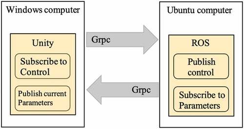
The raw data generated from unity is sent to Ubuntu OS through GRPC. The received data is constructed into ROS message type to be utilized in ROS communication. In terms of ROS topic list, PoseStamped, TwistStamped, and PointCloud2 represent the position, velocities, and lidar data, respectively. GPS position is transferred into ROS parameter as “/scenario_instance/local_origin_latitude” and “/scenario_instance/local_origin _longitude.” The main control of the vessel is carried out on ROS in Unbuntu OS. The concept of communication inside ROS can be simply described as “Publish” and “Subscribe.” Nodes publish or subscribe to topics that contain the information. Each topic has its message type defined by the ROS system.
Communication between ROS and Unity
To communicate between two independent equipment, a network framework is required. In Inter-Process Communication (IPC), there are several ways such as shared memory, message queue, PIPE, and socket. Among them, the socket type is widely used through rosbridge package. Rosbirdge makes ROS topics and services available over either standard TCP (Transmission control protocol) sockets or WebSocket as JSON format. It is convenient because it is provided by an API. But the more data is required, the harder it becomes to format the data.
Google Remote Procedure Call (GRPC)
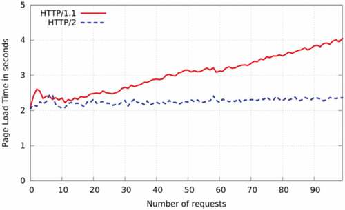
GRPC is utilised in order to communicate between Unity and ROS in our model. GRPC, which was developed by Google, is a way to communicate between server to client. It is an open-source framework that combines HTTP/2 and protocol buffer. The HTTP/2 is a strong advantage compared with socket/WebSocket. Protocol Buffer serialises the data to communicate, which means that data expression is changed into a byte unit. Compared with JSON format based on text, it requires less memory and increases the data transferring speed (Popić et al. Citation2016). The other characteristic of GRPC is HTTP/2. HTTP/1.1, which is the previous version, responds to clients when requests exist. Connections have to be made in every single request, so it is inefficient and shows slow speed (Fielding et al. Citation1999). On the other hand, enhanced HTTP/2 manage to send multiple messages into a single connection, which is more efficient than HTTP/1.1.
shows the page load time between HTTP/1.1 and HTTP/2. As the number of request increase, page load time of HTTP/1.1 is getting increase while HTTP/2 shows constant page load time. Compared with socket type communication (De Saxcé, Oprescu, and Chen Citation2015), GRPC is more suitable for our model considering real-time detection and control because of efficient bidirectional communication.
Figure 2. Comparing the loading time between HTTP/1.1 and HTTP/2 (De Saxcé, Oprescu, and Chen Citation2015).
Methodology
To control the model in Unity, it is required to construct a representative model in ROS. The model and control structure in ROS are described below.
Model definition
A vessel model follows three degrees of freedom. It is, however, assumed that the weather is culm, so there is not any pitch and yaw during the scenarios. The vessel is controlled by three forces and momentum, which are forward, backward, and momentum by z-axis. Four cameras and one lidar are equipped, and each camera visualise forward, backward, port, and starboard sides. Lidar is in the same position as cameras. More details of vessel coordinate systems are described below.
Coordinate system
Each joint in a robot has its coordinate system. When a robot wants to grab something, the coordinate system on the robot arm moves and rotates (Yoshikawa Citation1990). Position based on robot center frame needs to be converted into robot arm’s frame.
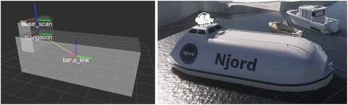
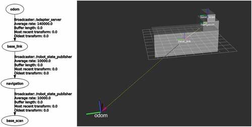
shows the virtual model created in ROS and the model in Unity. The position received from Unity represents that of the vessel center (base_link). The lidar data received, however, is based on the lidar equipment. In order to make a precise navigation map, the error between these two coordinate systems is corrected.
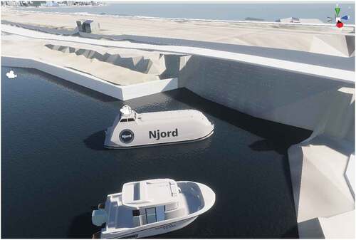
Figure 3. Vessel model with coordinate systems (base_link, navigation, base_scan) in ROS RVIZ, and Unity (NJORD Citation2021).
Another purpose of coordinate system transform is navigation. To navigate, the robot should recognise where he is. An absolute reference frame and local body-fixed frame are required to figure out position and rotation, which are represented as ,
, respectively. Point
is an arbitrary point of a rigid body. The homogenous coordinate
is zero for vector transformation and is one for points transformation. The body-fixed reference frame is described by homogenous transformation.
Where transformation matrix is described as,
Where is 3 × 3 orthogonal rotation matrix,
is the position of the origin of the body-fixed reference frame in the absolute reference frame (Yoshikawa Citation1990). This information is delivered by message type “Odometry” in ROS. shows how coordinates of vessel center is transformed by that of odometry. Fortunately, the vessel position is expressed by the coordinate system of a fixed frame (Odom) in Unity. So, this position is directly used to indicate the current position of the model in the global frame. On the other hand, the velocities are expressed by a body frame (Base_link). shows the coordinate system representing position of the vessel and equipments in ROS.
Figure 4. Coordinates transformation.
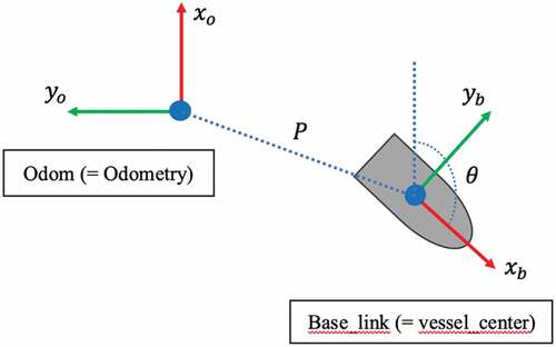
Figure 5. Constructed coordinates in the model.
Control structure
ROS supports a plenty of toolboxes, which are useful to understand and demonstrate robot communication status. RQT is one of the toolboxes, which show current communication status, signal value, transform of coordinate systems, etc. demonstrate current communication status while generating a map. Node is usually represented by the shape of “/xxx” and communicate with other nodes by messages. The below RQT graph shows the communication line between nodes.
Figure 6. Communication diagram by node while mapping (RQT).
“robot_state_publisher” is constructed to generate information of vessel coordinate systems and their joints. The vessel has a base link as “base_link”, and links “navigation” and “base_scan” are joint with it. Lidar is equipped in the “base_scan” frame. This node publishes message type “transform” as well. “ros_adapter” is a node that publishes the position, velocity of the model, and lidar information. The position of the vessel is published by the message type “geometry_msgs/PoseStamped,” which deliver the vessel position as x,y,z and orientation as x,y,z, w by homogenous coordinate. In the case of velocity, it is delivered by “geometry_msgs/TwistStamped,” which demonstrate linear velocities and angular velocities in each axis. The lidar information is delivered by the message type of ‘PointCloud2ʹ. ‘PointCloud2ʹ type message is converted into “LaserScan” type message to be utilised in the navigation package. “navigation” publishes the required vessel velocity to get to the target point based on Dijkstra and DWA (Dynamic-Window Approach) algorithms. In order to reach the ordered velocities, forces and momentums are controlled by the PID controller. Ordered forces and momentums are published through the ‘ros_clients’ node.
demonstrates the schematic diagram of a designed navigation system. Once the destination is ordered by the set of x, y in the fixed frame and heading, the global path is generated by considering a current position and the map. While the vessel navigates following a global path, real-time sensing for collision avoidance is carried out by considering the current position, Images from the camera, and Lidar information within a specific boundary.
Figure 7. Schematic diagram of the proposed autonomous navigation with object detection model.
Navigation
The main navigation system is based on open packages. Navigation, Pointcloud_to_laserscan, Yolov4-for-darknet_ros, gmapping are utilised to develop a navigation system. A Navigation package is an open package that enables robots to navigate autonomously. Dijkstra and Dynamic window approach (DWA) are utilised in global and local path planning, respectively. A detailed description of both algorithms is followed below. The gmapping package generates a map of where a robot is going to navigate globally, while a local map is updated by lidar data in real time. ROS receives lidar messages from Unity with the form of ‘sensor_msgs/PointCloud2ʹ. So, it should be converted into “sensor_msgs/LaserScan” in order to be utilised in gmapping and navigation packages. shows the simulation environment with the model and PointCloud projected in ROS rviz. Yolov4-for-darknet_ros package provides the ability to detect objects in real-time. Yolov4 is trained by our data set and the weights are derived from there. Original darknet provided the source where the father of YOLO services the YOLO model in open-source by darknet (Bochkovskiy and Wang Citation2020).
Figure 8. Simulation environment in the unity.
Global path planning
Dijkstra algorithm
Dijkstra algorithms find the shortest paths from a source node to a destination node. When the algorithm finds all distances from the initial node, the shortest path can be defined. The fundamental algorithm of Dijkstra can be described by a few steps. First, the distance of a source node is initialised as zero. Then, all distances of unvisited vertex V were defined as “infinity” and a previous vertex as “undefined.” Second, the distances of neighborhood nodes from an initial node are input. Third, the node which requires a minimum distance among unvisited nodes is selected. Fourth, the minimum distance considering other distances (sum of distances passing the other nodes) is updated. Fifth, it repeats the third and fourth procedures (Dijkstra Citation1959). Dijkstra algorithm is widely used to find the shortest paths in robots with the A star algorithm. A star algorithm shows relatively high searching speed without considering all nodes. Dijkstra, however, shows higher performances in terms of accuracy. Because it considers all nodes, while A star considers the nodes by heuristic search. In our model, the processing speed between the two methods is not too big relatively. Because the map is not huge. So, the Dijkstra algorithm is utilised instead of the A star algorithm. When a robot is placed in an unknown place, it is not available to calculate. So, to find the globally shortest path, a map should be pre-defined to calculate it. The virtual environment map is made by using the gmapping package, while the global map is provided by ECDIS in the case of real vessels.
Local path planning
VO (Velocity Obstacle)
In a previous project, VO (Velocity Obstacle) had been considered and tested as a local planning algorithm. VO is a simple and reliable collision avoidance method that has been developed constantly as RVO (Van Den Berg, Lin, and Manocha Citation2008) and HRVO (Snape et al. Citation2011).
The main idea of collision avoidance by VO is that VO is the area of all velocities, which can result in a collision with an obstacle (Fiorini and Shiller Citation1998); therefore, if a robot choose the outside of the VO area, the robot is free from collisions. However, there are limitations to implement it in our model.
The condition of applying VO is that the velocity and position of both two obstacles should be calculated. This is usually given by Radar. Radar is, however, not equipped in the model, which means that the model cannot measure the velocity of moving obstacles. So, local planning algorithms should be independent of external parameters.
DWA (Dynamic Window Approach)
DWA (Dynamic Window Approach) is a well-known method, which is widely applied in robot navigation. In order to apply DWA, it requires a robot velocity and a distance from obstacles, while VO is carried out by both velocities. Robots applied by the DWA algorithm optimise a local route by maximising the objective function.
DWA Objective equation. Where, heading is a standard to determine the progress, and it is maximised if the robot head for the target directly. dist is the distance between the robot and the closest obstacles on the trajectory. Small distance means that the robot is more likely to collide with an obstacle. So, the robot takes a roundabout way. vel is the forward velocity to get to the goal faster. is the function that can be controlled by users to change the rate of the weighted sum (Fox, Burgard, and Thrun Citation1997). In the moving obstacle collision avoidance point of view, the difference between VO and DWA is that VO eliminates the risk of collision by selecting velocity, which guarantees a free from the collision. On the other hand, DWA minimises the collision risk by maximising the distance from obstacles. So, the DWA algorithm is more practical due to the direct implementation of the parameter from LIDAR, which measures the distance from obstacles.
Mapping
In order to achieve autonomous navigation, it is essential to know the map of the navigation area.
Through the map, Robot knows where it is now, and then this can plan its next path. In the case of the vessel, it was provided by a physical map. Officers confirm the vessel’s position on the map by latitude and longitude. Nowadays, ECDIS (Electronic Chart Display and Information System) is available in the majority of vessels, and it is available to use this electronic map for autonomous navigation. In our model, gmapping package is utilised in order to make a global map.
Object detection
Different from object classification, Object detection is the way to specify the place and name of multiple objects within an image. In autonomous navigation, recognising the object is essential to navigate. When it is required to navigate following a specific route because of the draft, navigation should care about the position of buoys. When a vessel faces a dynamic object during navigating, the vessel acts in different ways in accordance with whether the objects are vessels or not. If the dynamic object is a vessel, the autonomous vessel should avoid collision according to the COLREGs. The cameras equipped in the vessel take a video and send a picture every second. In order to perform real-time decisions, image recognition should be fast and accurate. There are predominant and practical models introduced in the research area. RCNN (Region-based Convolutional Neural Network) and YOLO (You Only Look Once) are the ones.
RCNN is a model proposed by Ross Girshick, which can recognise the multiple objects in an image. The main idea is that many region proposals are generated up to 2000, and each one passes the CNN. Then these are classified by using class-specific linear SVMs (Support Vector Machine) (Girshick et al. Citation2015). This has been developed as fast-RCNN (Girshick Citation2015), Faster-RCNN (Ren et al. Citation2015), and Mask RCNN (He et al. Citation2017). The computing speed, which is one of the main drawbacks, has been improved by changing the structure of the model. The full image passes the CNN and then extract the fixed-length feature vector from the feature map by a region of interest (RoI), while the initial RCNN pass each object proposal pass the CNN. This reduces the time cost significantly. Faster RCNN is even more improved by changing the module of region proposal from selective-search base to RPN (Region Proposal Network), which enable the model into one end-to-end structure.
YOLO (You Only Looks Once) is introduced by Joseph Redmon at the University of Washington. Different from RCNN, YOLO is constructed with a single neural network to predict bounding box and class probabilities, which is inspired by the GoogLeNet model for image classification (Redmon et al. Citation2016). Thanks to the simple structure, it is much faster than R-CNN. There are other advantages compared with R-CNN. YOLO see the entire image while RCNN reasons locally. So, it has a smaller number of background errors.
In our model, YOLO version four is applied in order to detect makers. Speed is the main reason to choose the model. YOLO shows the highest real-time performance in models (Redmon et al. Citation2016) and shows dominant value in FPS (Frame Per Seconds). In real-time sensing, YOLO is the most appropriate model because navigation decisions should be carried out every second. RCNN has been developed but still demonstrate insufficient performance to use as a real-time model (Redmon et al. Citation2016).
Results and discussion
In this study, a reliable and efficient simulation environment for developing a navigation system is introduced. The simulation environment can not only overcome the space-time constraints but also be used to test risky situations. While developing a system, Nodes and message type communication provide developers with visualisation of current communication status intuitionally, which increase the productivity of the whole process.
A conventional navigation algorithm just takes the information of circumstances by numerical values. This is essential to treat the information inside computers. This process converting visual or complex information into numerical parameters, however, lost much other information. By applying object detection on the navigation system, the system directly uses visual information, which broadens the boundary of information. Detailed descriptions and results about the system are followed.
Navigation
Control system
The overall control can be simply divided into three modules. One is the navigation module, the other is the object detection module, and the other is the PID control module. The navigation module defines a global route by the Dijkstra algorithm, while the local cost map changes the local route when facing unexpected obstacles. Unexpected obstacles mean obstacles that do not exist during making the global map. So, avoiding any static obstacles or dynamic obstacles is carried out by DWA.
Below and shows an overall algorithm for making a global path and local path with object detection while represent the algorithm when detecting markers.
Figure 9. Projected environment by Lidar in ROS RVIZ.
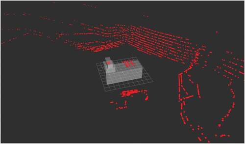
Figure 10. Algorithm for optimal route.
Figure 11. Algorithm for action by object detection.
While following the path for navigation, the vessel should consider the sign of markers. When a vessel detects a green lateral marker, it should pass the path putting the marker on the starboard side. Even though global path design optimal path, navigation package output desired velocity of the vessel and then, PID control continuously adjusts the forces and moment of the vessel to minimise the error between actual velocity and outputted velocity.
Object detection
Collecting and pre-processing images
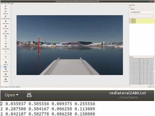
Images for training are collected in a Unity environment. Lots of markers were placed in arbitrary positions. The Images are saved every five seconds automatically. RGB values coming from the ROS message are saved in a specific folder. The script used for saving images is attached in the appendix. LabelImg is used in order to carry out labelling with a bounding box. Each labelled file with.txt extension consists of 5 components: class, x position, y position, width, height. shows lebelling programme ' LabelImg‘ and assigned position for markers.
Figure 12. LabelImg program for labelling and labeled text file (representing class, x position, y position, width, height).
Training
The model is trained by a computer equipped with INTEL i9 – 10980XE 3.00 GHz x 36, NVIDIA GeForce RTX 3090 and 32 GB RAM. NVIDIA Driver version is 470.57.02. CUDA 11.4 and cuDNN v8.2.2.26 are installed to utilised GPU in training. A total of 2,972 images are prepared to train the model. The numbers of train and validation data set are 2,522 images (85%) and 450 images (15%), respectively. To get a precise model, different hyperparameters are tested. The performances of models are compared by AP (Average Precision) with RP graph (Recall-Precision). mAP (mean Average Precision) is compared as well.
Performance
Among various YOLO models, YOLO v4 and YOLO v4 tiny models are trained and tested. Different learning rates, batch sizes with subdivision and resolution are tested. . shows loss and mAP of the YOLOv4 while training with various hyperparameters. on the other hand, shows those of the YOLO-tiny. In the case of batch size and subdivision, the value is restricted by the capacity of the GPU. In our cases, GPU has 32 GB, and it allows to allocate a maximum of 64 batch size with 8 subdivisions when applying 640 × 320 resolution. If a bigger batch size or higher resolution is implemented, warning “CUDA out of memory” happen.
Figure 13. YOLO v4 models – Training process (red line – mAP, blue line – Loss).
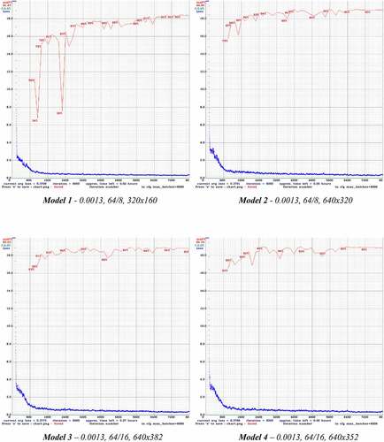
Figure 13. Continued.
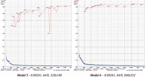
Figure 14. YOLO v4 – tiny models – Training process (red line – mAP, blue line – Loss).
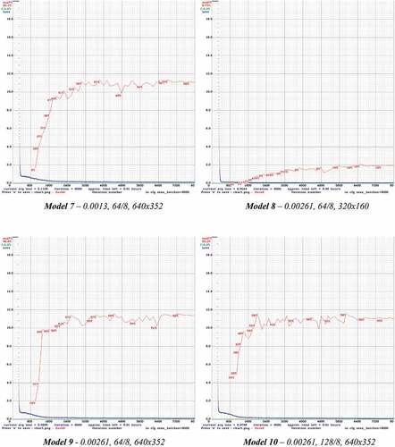
There is a trade-off between precision and processing speed. YOLO-tiny is the model, which reduces the number of convolutional layers to increase processing speed. It handles images with 155 fps, which is three times faster than that of YOLO (Redmon et al. Citation2016). However, because of thinner convolutional layers, it generally shows less precision compared with YOLO v4. Below represents performances by various hyperparameters.
Table 1. Performances of YOLOv4 by Hyperparameter
Compared with models 1 and 2 (5 and 6), it is clear that the model which has higher resolution represents higher performances in every measurement. Because the model has less loss with respect to data features. YOLOv4 model 2 made up 94.87% mAP and 0.89 F1-score, which is predominant performance to detect objects. Total training times are around 8 hours in our environment.
As can be seen in , YOLOv4 – tiny represent relatively low mAP compared with all other YOLOv4 models. mAP of the YOLOv4-tiny model with the biggest batch size (128), and 640 × 352 resolution represents only 55.16 percentages. In terms of detection time, the total detection time of YOLOv4-tiny shows 2 seconds, which is half that of YOLOv4. Total training time for YOLOv4-tiny models takes around 2 hours, which is one fourth of YOLOv4.
Table 2. Performances of YOLOv4-tiny by Hyperparameter
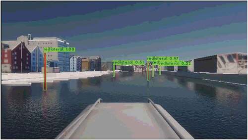
As can be seen in , trained model is tested in unseen pictures. shows confidence by lateral. The confidence of all laterals represents more than 95% within 60 meters. It suddenly plunges between 60 and 80 meters. Even though the confidence maintains around 50% at distance of more than 100 meters, 50% is equal to the random probability. Therefore, the model can be utilised within 100 meters showing more than 60% confidence.
Figure 15. Confidence by lateral.
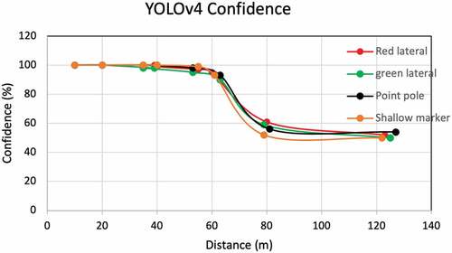
Figure 16. Testing by unseen picture (red lateral: confidence), YOLOv4.
Limitations
The Unity environment does not have the ability to simulate collision yet. In order to make the simulation environment more similar to reality, a collision body should be considered. So, when the model collides with obstacles, it can trigger the signal that a collision happens. The vessel can successfully navigate based on the map created. There is, however, the mandatory rule, which vessels should follow known as COLREGs. In the case of the fastest trajectory to a goal which does not follow the COLREGs, the autonomous vessel should put preference in the rule. In order to embody the task, the algorithm should be modified.
Even though the model follows three degrees of freedom, the effect of yaw is ignored in this study. However, the vessel’s heading is continuously changed by the effect of current and wind. The model should be tested on various weather conditions.
Constructing a vessel system should consider many sensors. All parameters from sensors should be properly adjusted and formed in order to be used in navigation. At that point, more settings should be done and tested to figure out optimum set-up. When it comes to success in setting up the parameters, different navigation algorithms should be considered. The Majority of vessels are equipped with radar. These enable a vessel to take the information of dynamic obstacles like heading and speed. These are very valuable to predict the movement of obstacles. While applying DWA as local panning algorithms, other algorithms like VO can be tested and compared. Moreover, there are many attempts to applying reinforcement learning in the vessel navigation. Even though Direct application of the Deep Reinforcement Learning (DRL) into navigation have uncertainties, the valuable model applying a DRL in the boundary of decision-making stage with grid map approach enable a vessel to navigate by following specific algorithm while the vessel has ability to reflect experiences during various encounter circumstances (Woo and Kim Citation2020). This different approach can be a great option in the prior stage of collision avoidance for the vessel to have an ability of active decisions.
Future study
PID control is a reliable method, which has been widely used. Even though there is a general PID tuning method like the Ziegler-Nichols method (Ziegler and Nichols Citation1942), the weakness of PID is, however, that it should be practically adjusted to find out the optimal setting: parameters such as proportional gain, integral gain, and derivative gain. More tests are required to achieve reliable control from a navigation package to a PID package.
There is a trade-off between accuracy and speed. Even though YOLO is currently a suitable way to use in real-time sensing, it has limited performance to use because of its accuracy. R-CNN shows better accuracy compared with YOLO. During vessel navigation, a small error can lead to a huge economic risk. In order to prevent the accident from the error, accurate detection is important. Therefore, other object detection models should be considered and tested. Not only YOLO and RCNN but also other object detection models are continuously improved by year and year (Liu et al. Citation2020). YOLO is improved with version 4 in 2020 by increasing accuracy with different bags of Specials and Freebies (Bochkovskiy, Wang, and Liao Citation2020). Mask R-CNN is now applicable to make masks, not the bounding box (He et al. Citation2017). A new novel method called Multi-Level Feature Pyramid Network (MLFPN) is proposed to extract features from input images (Zhao et al. Citation2019) by considering the characteristics of each model, an optimal model should be chosen.
Conclusions
In this research, an autonomous vessel is introduced in a simulation environment. Based on the research study discussed in the preceding sections, the following conclusions can be drawn:
ROS and UNITY is an efficient developing and simulation environment. Representing the system as a set of nodes is easy to understand communication status and to find out problem points. Utilising a unity as a simulation environment erases the space-time constraints in testing process and provides optimal environment for testing risky situations.
Throughout the case study, the navigation system with Dijkstra and DWA algorithms has been made and proven to be a successful system for autonomous navigation on the vessel.
Object detection model YOLO v4 enhances support navigation system to be active by recognising object. Detection accuracy shows remarkable performance with 94% for distinguishing sea-markers, which overwhelm that of human being. Within 100 meters, the confidence of the model is more than 97%. It, however, rapidly drop after 60 meters. The model with consistent performance can be a part of autonomous system or utilised to support current navigation system.
This project can be considered as a pilot study that brings directions and methods to move towards the realisation of autonomous marine vehicles with excellent performance in object detection, which is a fundamental element to be equipped with those ships.
Disclosure statement
No potential conflict of interest was reported by the author(s).
References
- Bartneck, C., M. Soucy, K. Fleuret, and E. B. Sandoval “The Robot engine—Making the Unity 3D Game Engine Work for HRI.” 2015 24th IEEE International Symposium on Robot and Human Interactive Communication (RO-MAN), 2015. IEEE, 431–437.
- Bochkovskiy, A., and C.-Y. Wang 2020. YOLOv4 darknet- Git Hub source
- Bochkovskiy, A., C.-Y. Wang, and H.-Y. M. Liao 2020. “Yolov4: Optimal Speed and Accuracy of Object Detection.” arXiv preprint arXiv:2004.10934.
- Boschert, S., and R. Rosen. 2016. “Digital Twin—the Simulation Aspect.” Mechatronic Futures, no. Springer. https://doi.org/10.1007/978-3-319-32156-1_5
- Chakravarthy, A., and D. Ghose. 1998. “Obstacle Avoidance in A Dynamic Environment: A Collision Cone Approach.” IEEE Transactions on Systems, Man, and Cybernetics-Part A: Systems and Humans 28: 562–574.
- Chauvin, C., S. Lardjane, G. Morel, J.-P. Clostermann, and B. Langard. 2013. “Human and Organisational Factors in Maritime Accidents: Analysis of Collisions at Sea Using the HFACS.” Accident Analysis & Prevention 59: 26–37.
- Codd-Downey, R., P. M. Forooshani, A. Speers, H. Wang, and M. Jenkin “From ROS to Unity: Leveraging Robot and Virtual Environment Middleware for Immersive Teleoperation.” 2014 IEEE International Conference on Information and Automation (ICIA), 2014. Hailar, China: IEEE, 932–936.
- Conte, G., D. Scaradozzi, D. Mannocchi, P. Raspa, L. Panebianco, and L. Screpanti. 2018. “Development and Experimental Tests of a ROS Multi-agent Structure for Autonomous Surface Vehicles.” Journal of Intelligent & Robotic Systems 92: 705–718.
- De Saxcé, H., I. Oprescu, and Y. Chen “Is HTTP/2 Really Faster than HTTP/1.1?” 2015 IEEE Conference on Computer Communications Workshops (INFOCOM WKSHPS), 2015. Hong Kong, China: IEEE, 293–299.
- Dijkstra, E. W. 1959. “A Note on Two Problems in Connexion with Graphs.” Numerische mathematik 1: 269–271.
- DNVGL. 2018. “Autonomous and Remotely Operated Ships.” Class Guideline DNVGL-CG-0264 https://rules.Dnvgl.com/docs/pdf/DNVGL/CG/2018-09/DNVGL-CG-0264.Pdf, https://rules.Dnvgl.com/docs/pdf/DNVGL/CG/2018-09/DNVGL-CG-0264.Pdf
- Evensen, M. H. 2020. Safety and Security of Autonomous Vessels. Based on the Yara Birkeland Project. University of Bergen.
- Fernandes, E., P. Costa, J. Lima, and G. Veiga “Towards an Orientation Enhanced Astar Algorithm for Robotic Navigation.” 2015 IEEE International Conference on Industrial Technology (ICIT), 2015. IEEE, 3320–3325.
- Fielding, R., J. Gettys, J. Mogul, H. Frystyk, L. Masinter, P. Leach, and T. Berners-lee 1999. Hypertext Transfer protocol–HTTP/1.1. RFC 2616, june.
- Fiorini, P., and Z. Shiller. 1998. “Motion Planning in Dynamic Environments Using Velocity Obstacles.” The International Journal of Robotics Research 17: 760–772.
- Fox, D., W. Burgard, and S. Thrun. 1997. “The Dynamic Window Approach to Collision Avoidance.” IEEE Robotics & Automation Magazine 4: 23–33.
- Girshick, R. “Fast R-CNN.” Proceedings of the IEEE international conference on computer vision, 2015. 1440–1448.
- Girshick, R., J. Donahue, T. Darrell, and J. Malik. 2015. “Region-based Convolutional Networks for Accurate Object Detection and Segmentation.” IEEE Transactions on Pattern Analysis and Machine Intelligence 38: 142–158.
- He, K., G. Gkioxari, P. Dollár, and R. Girshick “Mask R-CNN.” Proceedings of the IEEE international conference on computer vision, 2017. 2961–2969.
- Jeon, M., J. Park, and J. Woo. 2019. “Development of HHI’s Advanced Navigation Assistance System for Safe Voyage.” IFAC-PapersOnLine 52: 111–113.
- Liu, L., W. Ouyang, X. Wang, P. Fieguth, J. Chen, X. Liu, and M. Pietikäinen. 2020. “Deep Learning for Generic Object Detection: A Survey.” International Journal of Computer Vision 128: 261–318.
- NASA 2021. “VIPER’s Mission Operations.” chapter- Software: Creating and Building on Open-Source Code.
- NJORD 2021. https://www.njordchallenge.com/the-competition/rules
- Popić, S., D. Pezer, B. Mrazovac, and N. Teslić “Performance Evaluation of Using Protocol Buffers in the Internet of Things Communication.” 2016 International Conference on Smart Systems and Technologies (SST), 2016. IEEE, 261–265.
- Quigley, M., K. Conley, B. Gerkey, J. Faust, T. Foote, J. Leibs, R. Wheeler, and A. Y. Ng “ROS: An Open-source Robot Operating System.” ICRA workshop on open source software, 2009. Kobe, Japan, 5.
- Redmon, J., S. Divvala, R. Girshick, and A. Farhadi “You Only Look Once: Unified, Real-time Object Detection.” Proceedings of the IEEE conference on computer vision and pattern recognition, 2016. 779–788.
- Ren, S., K. He, R. Girshick, and J. Sun. 2015. “Faster R-CNN: Towards Real-time Object Detection with Region Proposal Networks.” Advances in Neural Information Processing Systems 28: 91–99.
- ROS 2020. Metrics-report-2020-07.
- Sita, E., C. M. Horváth, T. Thomessen, P. Korondi, and A. G. Pipe “ROS-Unity3D Based System for Monitoring of an Industrial Robotic Process.” 2017 IEEE/SICE International Symposium on System Integration (SII), 2017. IEEE, 1047–1052.
- Snape, J., J. Van Den Berg, S. J. Guy, and D. Manocha. 2011. “The Hybrid Reciprocal Velocity Obstacle.” IEEE Transactions on Robotics 27: 696–706.
- Van Den Berg, J., M. Lin, and D. Manocha “Reciprocal Velocity Obstacles for Real-time Multi-agent Navigation.” 2008 IEEE International Conference on Robotics and Automation, 2008. IEEE, 1928–1935.
- Wang, Z., and X. Xiang “Improved Astar Algorithm for Path Planning of Marine Robot.” 2018 37th Chinese Control Conference (CCC), 2018. IEEE, 5410–5414.
- Woo, J., and N. Kim. 2020. “Collision Avoidance for an Unmanned Surface Vehicle Using Deep Reinforcement Learning.” Ocean Engineering 199: 107001.
- Yoshikawa, T. 1990. Foundations of Robotics: Analysis and Control. MIT press.
- Zhao, Q., T. Sheng, Y. Wang, Z. Tang, Y. Chen, L. Cai, and H. Ling “M2det: A Single-shot Object Detector Based on Multi-level Feature Pyramid Network.” Proceedings of the AAAI conference on artificial intelligence, 2019. 9259–9266.
- Ziegler, J. G., and N. B. Nichols. 1942. “Optimum Settings for Automatic Controllers.” In Trans. ASME, 64. https://doi.org/10.1115/1.2899060