
 ?Mathematical formulae have been encoded as MathML and are displayed in this HTML version using MathJax in order to improve their display. Uncheck the box to turn MathJax off. This feature requires Javascript. Click on a formula to zoom.
Abstract
Ultra-hard cutting materials such as polycrystalline diamond (PCD) and cubic boron nitride (PcBN) are increasingly being used as cutting tools in machining. The finishing of cutting tools is challenging due to their mechanical and thermal properties. Both mechanical preparation processes such as grinding and brushing are used to prepare the final contour of the tools. All processes affect the subsurface of the cutting edge, thermally, mechanically, or both. In addition to influencing the cutting edge microgeometry and topography, it is also to be expected that the residual stress state is influenced. In particular for the highly loaded cutting edge, the residual stress state is of major interest, since high cyclic load stresses occur during cutting. A measurement using conventional X-ray diffraction to determine the residual stress state in the cutting edge is not possible due to the very small surface and the strong curvature. For this reason, the influence of the cutting edge preparation methods grinding and brushing for PCD and PcBN on the residual stress state is determined in this work using Raman spectroscopy. For this purpose, the preparation-induced peak shift in the Raman spectrum is determined. This is then converted into absolute residual stresses using previously determined conversion factors.
1. Introduction
The ultra-hard cutting material phase leads to a high hardness of the composites PcBN and PCD. However, it also makes it very difficult to machine with mechanical manufacturing processes. One possibility of machining these cutting materials in a mechanically and geometrically defined way is to grind them with diamond grains (Behrens, Citation2016; Tso & Liu, Citation2002). The disadvantage of this method is the high level of grinding wheel wear, which in case of PcBN can be many times the removed material volume from the tool (Leahy, Citation2013) and can be considerably higher when machining PCD (Friemuth, Citation2002). If this process is examined in more detail, it can be seen that the removal mechanism is not entirely mechanical. At high temperatures, the diamond in the PCD graphitizes and can subsequently be removed as the mechanically less demanding graphite (Schindler, Brocker, Klocke, & Mattfeld, Citation2016). It becomes clear here that the subsurface of the finished tool has been subjected to additional thermal stress due to mechanical processing. Grinding PcBN is much easier to implement due to its lower hardness and therefore also differs in terms of its material separation mechanisms which is described as microdestruction of the surface by the grinding wheel (Mamalis, Horvath, & Grabchenko, Citation2000). Due to the higher thermal stability of PcBN, a thermal influence on the subsurface is less probable (Xikun et al., Citation2007).
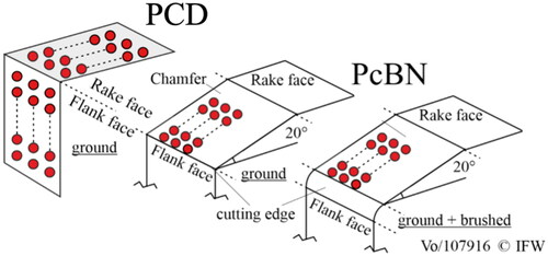
PCD machining is already completed after grinding, as the sharpest possible cutting edge is necessary for use in aluminium machining, see for example (Brinksmeier, Fangmann, & Rentsch, Citation2011; Tsao & Hocheng, Citation2007). In PcBN machining, a ground chamfer is necessary to stabilize the cutting edge, which optimises chip formation and increases tool life (Fang & Wu, Citation2005; Klocke, Brinksmeier, & Weinert, Citation2005; Kress, Citation2007). Furthermore, a cutting edge rounding is used to protect the cutting edge from micro chipping (Özel, Karpat, & Srivastava, Citation2008). For this purpose, the cutting edge is machined by means of diamond brushes and is thus abrasively rounded. The influence of the machining process on the residual stress state has already been investigated for PCD for the EDM process. Rahim et al. show high tensile residual stresses in the cutting edge area measured by Raman spectroscopy (Rahim, Pourmoslemi, Ding, & Mo, Citation2013). Furthermore, Sotillo et al. found an influence of laser machining on the compressive residual stresses determined by Raman spectroscopy, which can be reduced (Sotillo et al., Citation2017). According to Li et al., the grinding of PCD tools leads to compressive residual stresses or low tensile residual stresses (Li, Rahim, Ding, & Sun, Citation2016).
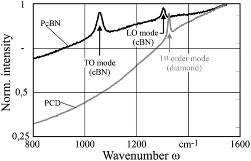
For the measurement of load or residual stresses, the sensitivity of the peak position of the transverse-optical (TO) or logitunial-optical (LO) modes of cubic boron nitride and the first mode of diamond can be used. All modes shift to higher wavenumbers when a compressive load stresses is applied (Boppart, Silvera, & van Straaten J, Citation1985; Mitra, Brafman, Daniels, & Crawford, Citation1969; Ono, Mibe, Hirao, & Ohishi, Citation2015). On the basis of known conversion factors, the resulting residual stresses can be calculated (Catledge, Yogesh, Ladi, & Rai, Citation1996; Sanjurjo, López-Cruz, Vogl, & Cardona, Citation1983). The measurability of residual stresses in coatings by Raman spectroscopy has already been demonstrated on coatings (Breidenstein, Vogel, Behrens, Dietrich, & Andersson, Citation2022).
It is evident that the influence of different preparation methods on the subsurface of PCD and PcBN has been investigated and basic influences have been identified. However, the influence of the process parameters during grinding or brushing has not yet been extensively investigated and is the subject of this paper.
2. Materials and methods
2.1. Cutting materials
PCD and PcBN cutting materials were used for the investigations. PCD has diamond grains with a diameter of dg = 4 µm and a diamond content of 90%. Due to the manufacturing process, the 0.5 mm thick PCD layer is soldered on a 1.1 mm thick tungsten carbide substrate (data sheet information). The PCD grade is characterized by a good measurability by means of Raman spectroscopy and the later machining of highly eutectic aluminium alloys with a high silicon content. PcBN with a cBN content of 85% was used, which has an AlWCoB binder and a cBN grain diameter of dg = 2 µm (data sheet information). Due to the high cBN content, reproducible Raman spectroscopy measurements are possible. For the grinding process, indexable insert bodies of type CNGA 120408 were previously provided with tips made of the above-mentioned cutting materials to enable machining on a tool grinding machine.
2.2. Preparation processes
2.2.1. Grinding process
A Wendt WAC Centro 715 CBN tool grinding machine, specialized in the machining of indexable inserts, was utilized for grinding PCD and PcBN cutting materials. The grinding tool used was a Saint Gobain D15A PCX-PRIME grinding wheel, possessing a diamond grain diameter of dg = 15 µm and a ceramic bonding. On this machine, two process parameters can be varied: the cutting speed vc and the feed rate f, which acts orthogonal to the machined surface.
When machining PcBN tools, the feed rate was varied in two steps (f = 6 and 8 mm/min) and the cutting speed in three steps (vc = 10, 15, and 20 m/s). Both, the flank face and a chamfer with an angle of 20° and a length of l = 200 µm were produced by grinding.
Due to strong graphitization of the grinding wheel during PCD machining, reduced cutting speeds were applied (vc = 10/12.5/15 m/s). For the same reason, the feed rate was fixed at f = 6 mm/min. As PCD tools do not have a protective chamber as it is common with PcBN tools, only the flank face was ground.
2.2.2. Brushing process
In addition to the grinding process, PcBN tools were rounded using a brushing process to stabilize the cutting edge. An in-house development, based on an industrial robot, was employed for this purpose, ensuring reproducible brushing (Rehe, Citation2015). In this process, the tool is moved into the diamond brushes using an industrial robot and is thus brushed in a defined orientation. The brushing speed vb was varied in 3 steps (vb = 11.8/21.6/31.4 m/s). Tools were brushed that have been ground at both cutting speeds.
2.3. Raman spectroscopy
Raman spectra were obtained using a Bruker Santerra II spectrometer on an Olympus BX51 microscope with a green laser (λ = 532 nm) and a 100× magnification objective lens. The measurements followed the settings from .
Table 1. Measurement settings for Raman spectroscopy
For the PcBN tools machined by grinding, 30 measurements were performed on the chamfer near the cutting edge. The first 3 measurements were taken directly at the transition to the cutting edge with a distance of 2 µm parallel to the cutting edge, the other measurements with a distance of 2 µm from each other on the chamfer (). The same procedure was also carried out for the PCD tools machined by grinding. Here, however, the machined flank and the unmachined rake face were measured 30 times for each grinding process parameter variation. After brushing, the measurements were repeated as shown in . The measuring point diameter dM was approx. 2 µm. The peak positions in the diamond (ω ≈ 1,330 cm−1) and the cBN (ω ≈ 1305 cm−1) spectra were then determined using the Fityk program after adjusting the background using a polynomial baseline correction (Wojdyr, Citation2010).
Figure 1. Measuring positions Raman spectroscopy.
3. Results
3.1. Raman-Spectroscopy
3.1.1. Ground and brushed tools
After the machining of PCD tools, Raman measurements were performed on the rake and flank surfaces as described and the spectra were evaluated accordingly. The spectra of the two cutting materials are shown as an example in .
Figure 2. Raman-spectra of cBN and diamond.
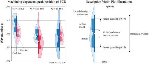
The results of the measurements described in Section 2.2 are shown in as violin plots. Violin plots are used because of the high spread of the measurements. The explanation of a vioin plot is shown on the right in the same figure. The peak position on the non-machined rake face shows a change to lower wavenumbers at vc = 12.5 m/s in relation to the mean value, with a high standard deviation at the same time. At a higher cutting speed, however, the shift normalizes again towards a wavenumber close to ω = 1,334 cm−1. If, however, the flank face finished by grinding is considered, there is a clear trend from a peak position significantly at higher wavenumbers than the peak position on the rake face at vc = 10 m/s, moving towards a comparable peak position at vc = 15 m/s. If the cutting speed is increased further, the mean value tends to shift further towards lower wavenumbers, while at the same time the standard deviation increases sharply and thus the trend can only be estimated.
Figure 3. Influence of grinding on PCD peak position.
After grinding, 30 measurements were carried out on the ground chamfer of the PcBN tools at different cutting speeds and feed rates as described. If the mean value in is considered, there is no visible influence with regard to the cutting speed. The peak position of the LO (transversal optical) mode remains in the range between ω = 1,306.7 and 1,307 cm−1. However, increasing the feed rate from f = 6 to 8 mm/min shows a trend towards lower wavenumbers across all cutting speeds.
Figure 4. Influence of grinding on cBN peak position LO-Mode.
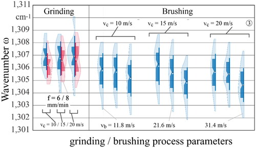
The tools, which were previously produced with a feed rate of f = 6 mm/min, are now machined at a low brushing speed of vb = 11.8 m/s, which shows a further shift of the peak position to lower wavenumbers. A trend with regard to the initial grinding processing is not recognizable. With increasing brushing speed to vb = 21.6 m/s and finally to 31.4 m/s the trend of shifting the peak position to lower wavenumbers continues. The peak thus shifts to a mean value between ω = 1,304.6 and 1,305.2 cm−1. The variation range of the determined peak positions follows this trend. It should be noted, however, that the mean values at the different brushing speeds are within the standard deviations of the other brushing speeds. Only at high brushing speeds a clear difference to the unbrushed tool can be seen in on the right, where the mean value lies outside the standard deviation of the unbrushed tools.
In order to establish a direct relationship between the peak shifts determined and the residual stresses causing them, the cutting materials were exposed to a load stress. This was done with the use of a 4-point bending device as shown schematically in . The load stresses on the surface were determined using XRD (X-ray diffraction). In parallel, the Raman spectrum was recorded and the peak position of the LO mode of cBN and the first mode of diamond were determined as described above. If the peak positions are plotted over the measured load stresses, the correlation shown in emerges. Compressive load stresses at the surface lead to a shift to higher wavenumbers.
Figure 5. Setup and determination of the conversion factors.
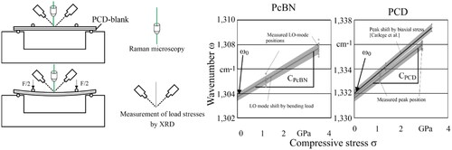
Based on the slope of the linear interpolation, a conversion factor CPcBN for PcBN and CPCD for PCD can be determined. Furthermore, a stress-free wavenumber ω0 can be determined for both cutting materials by extrapolation, in other words, a wavenumber ω that would be present in an ideally stress-free cutting material. If the shift of the peak and thus the slope of the linear regression is compared with literature values from Catledge et al., an almost parallel course is shown (Catledge et al., Citation1996). The deviation can be explained both by measurement-device deviations and by a deviating peak detection by means of Gauss-fit. The determined conversion factors and extrapolated peak positions of a stress-free state are shown in .
Table 2. Conversion parameters C and stress-free wavenumber ω0.
A detailed explanation of the procedure for determining the conversion factor and a detailed comparison with existing conversion factors from the literature can be found in (Breidenstein & Vogel, Citation2024)
4. Discussion
The analysis of high hardness cutting materials by Raman spectroscopy has been able to show influences of the tool preparation processes grinding and brushing on peakpositions. As shown in the previous evaluation of the results, clear tendencies of both the preparation process and most of the process parameters are recognizable. However, this influence is covered by the high standard deviation of the determined peak positions. Each stress value σ in the cutting material can be assigned to a peak position ωs in the Raman spectrum. Using the stress-free peak position ω0 and the stress-dependent conversion factor C, the resulting residual stress value σRS can be calculated according to the following EquationEquations (1)(1)
(1) and Equation(2)
(2)
(2) adapted from (Catledge et al., Citation1996):
(1)
(1)
(2)
(2)
If the averaged peak positions from the previously performed measurements are converted into absolute residual stress values using the conversion factors, the residual stress values for the ground PcBN tools in are obtained. As it can already be seen directly from the peak positions, there is no clear influence of the cutting speed when grinding PcBN. However, at all cutting speeds, strong compressive residual stresses between σRS = −2.6 and −2.9 GPa are present after machining. The reason for this is that a higher feed rate leads to an increase in the single grain chip thickness, and this, in turn, increases the temperature in the contact zone due to friction. This increased thermal effect induced by friction overlays the mechanical effect of the grinding process, which essentially causes compressive residual stresses.
Figure 6. Residual stresses converted from Raman spectra after grinding and brushing PcBN.
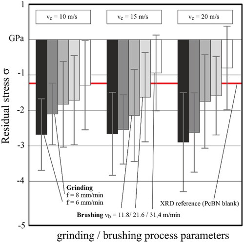
If the tools that were ground at a low feed rate and therefore have high initial compressive residual stresses are also machined using the brushing process, a decrease in compressive residual stresses is already seen at low brushing speeds (vb = 11.8 m/s) at all initial cutting speeds. If the brushing speed is increased to vb = 21.6 or 31.4 m/s, this trend continues and leads to residual stresses between σRS = −0.8 and −1.3 GPa. This is almost one third of the previously present compressive residual stresses. Originally, the mechanical process of brushing was expected to increase compressive residual stresses as it is kinematically similar to abrasive blasting, which has been shown to increase the residual stress state in PVD coatings in previous studies (Breidenstein et al., Citation2022). However, it should be noted that brushing is machining with a bonded grain and blasting with a non-bonded grain. This leads to cutting material with high compressive residual stresses being removed near the surfaces and unaffected cutting material being exposed. Raman measurements on samples prepared by manual polishing for the bending test and thus only minimally influenced by the preparation process show peak positions in the range ωs = 1,305.1 ± 0.34 cm−1 and residual stresses of σRS = −1.35 GPa determined by XRD. The subsurface properties of the brushed tools thus converge with the unprepared cutting material. Furthermore, it can be stated that the brushing process cannot mechanically induce any further compressive residual stresses into the cutting material. This can be explained by the high hardness of cBN, which does not allow any plastic deformation caused by the brushing process.
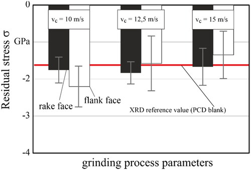
Considering the ground PCD tools and using the peak positions determined from , absolute residual stress values were obtained by applying the conversion factor C and shown in . As already seen in the peak positions in , grinding of the PCD tools does not influence the residual stress state on the rake face. Regardless of the cutting speed, measurements near the cutting edge show no influence of the cutting speed. However, if the machined flank face is considered, the converted residual stresses show a dependency. With increasing cutting speed vc, the compressive residual stresses σ decrease. The reason for this can be found in the increasing temperature in the contact zone between the PCD tool and the diamond grinding wheel at increased cutting speed, especially since the removal mechanism in grinding PCD tools is fundamentally related to the thermally induced diamond graphitization (Schindler, Citation2015; Schindler et al., Citation2016). The graphite formed was completely removed mechanically by the grinding wheel and could not be detected in the Raman spectrum.
Figure 7. Mean residual stresses converted from Raman spectra after grinding PCD.
In brief, the mechanical preparation methods involving grinding and brushing of PcBN tools show a trend towards influencing the peak positions, which correlate with the induced compressive residual stress state. Thermal influences encountered during grinding tend to reduce the compressive residual stresses within the machined area. On the other hand, the brushing process, being entirely mechanical, serves to remove stressed material without significantly reinducing compressive residual stresses. Comparisons between these transformed residual stresses and the initial residual stress states determined by XRD suggest that the resultant residual stress values are plausible.
5. Conclusion
The investigations have shown that the cutting-edge preparation processes of grinding and brushing have an influence on peak positions within the Raman spectrum and thus on the residual stress state. When considering both the peak shifts in the spectrum and the converted residual stress states, it is apparent that the grinding process increases the compressive residual stresses in the PcBN tools compared to the initial state of the unprocessed and non-separated cutting material blank. However, an influence of the cutting speed on the Raman spectrum and thus on the residual stresses could not be demonstrated in the context of this investigation. Nevertheless, when considering the mechanical process of brushing, it is evident that there is a decrease in the resulting compressive residual stresses, which can be explained removing material from the tool surface, thus exposing material unaffected by the grinding process.
The machining of PCD by grinding further shows that the cutting speed tends to have an influence on the residual stresses on the machined flank face, especially when compared with the non-machined rake face. The reduced compressive residual stresses at higher cutting speeds vc can be explained by thermal effects during machining. Lower cutting speeds increase the compressive residual stresses compared to the non-machined rake face. This suggests that a variation in cutting speed allows for the targeted adjustment of the residual stress state, which can be used to influence the tool life of PcBN and PCD tools.
The aim of further research is to produce tools with significantly different compressive residual stress states and to use these in the machining of hardened 100Cr6 and AlSi10Mg to demonstrate the influence of residual stresses on the wear behaviour of cutting tools.
Acknowledgments
The authors would like to thank the German Research Foundation (DFG) for funding research project BR 2967/22-1 “Influence of preparation-induced residual stresses in the cutting edge of cutting tools on the wear behavior of extremely hard cutting materials.”
Disclosure statement
No potential conflict of interest was reported by the authors.
References
- Behrens, L. (2016). Schleifen von PCBN. (Doctoral dissertation) Gottfried Wilhelm Leibniz Universität, Hannover. https://doi.org/10.15488/8638
- Boppart, H., Silvera, I. F. & van Straaten J. (1985). Raman spectra of diamond at high pressures. Physical Review. B, Condensed Matter, 32(2), 1423–1425. https://doi.org/10.1103/PhysRevB.32.1423
- Breidenstein, B., & Vogel, N. (2024). Locally resolved stress measurement in the ultra-hard composites polycrystalline diamond and polycrystalline cubic boron nitride. Forschung im Ingenieurwesen, 88(1), 5. https://doi.org/10.1007/s10010-024-00726-6
- Breidenstein, B., Vogel, N., Behrens, H., Dietrich, M., & Andersson, J. M. (2022). Determination of local residual stress on post-treated TiAlN-coated tungsten carbide tools. Journal of Surface Investigation: X-ray, Synchrotron and Neutron Techniques, 16(4), 663–671. https://doi.org/10.1134/S1027451022040231
- Brinksmeier, E., Fangmann, S., & Rentsch, R. (2011). Drilling of composites and resulting surface integrity. CIRP Annals Manufacturing Annals, 60(1), 57–60. https://doi.org/10.1016/j.cirp.2011.03.077
- Catledge, S. A., Yogesh, K. V., Ladi, R., & Rai, G. (1996). Micro-Raman stress investigations and X-ray diffraction analysis of polycrystalline diamond (PCD) tools. Diamond and Related Materials, 5(10), 1159–1165. https://doi.org/10.1016/0925-9635(96)00534-1
- Fang, N., & Wu, Q. (2005). The effects of chamfered and honed tool edge geometry in machining of three aluminum alloys. International Journal of Machine Tools and Manufacture, 45(10), 1178–1187. https://doi.org/10.1016/j.ijmachtools.2004.12.003
- Friemuth, T. (2002). Herstellung spanender Werkzeuge. (Postdoctoral dissertation) Gottfried Wilhelm Leibniz Universität, Hannover.
- Klocke, F., Brinksmeier, E., & Weinert, K. (2005). Capability profile of hard cutting and grinding processes. Cirp Annals, 54(2), 22–45. https://doi.org/10.1016/S0007-8506(07)60018-3
- Kress, J. (2007). Auswahl und Einsatz von polykristallinem kubischem Bornitrid beim Drehen, Fräsen und Reiben. (Doctoral dissertation) Universitat Dortmund.
- Leahy, W. (2013). CBN-Werkstoff mit formkontrolliertem Bruchverhalten. Ein neues Haus fuer Innovationen. Werkstatt und Betrieb, 3, 70–72.
- Li, G., Rahim, M. Z., Ding, S., & Sun, S. (2016). Performance and wear analysis of polycrystalline diamond (PCD) tools manufactured with different methods in turning titanium alloy Ti-6Al-4V. The International Journal of Advanced Manufacturing Technology, 85(1-4), 825–841. https://doi.org/10.1007/s00170-015-7949-6
- Mamalis, A. G., Horvath, M., & Grabchenko, A. I. (2000). Diamond grinding of super-hard materials. Journal of Materials Processing Technology, 97(1-3), 120–125. https://doi.org/10.1016/S0924-0136(99)00358-1
- Mitra, S. S., Brafman, O., Daniels, W. B., & Crawford, R. K. (1969). Pressure-induced phonon frequency shifts measured by Raman scattering. Physical Review, 186(3), 942–944. https://doi.org/10.1103/PhysRev.186.942
- Ono, S., Mibe, K., Hirao, N., & Ohishi, Y. (2015). In situ Raman spectroscopy of cubic boron nitride to 90 GPa and 800 K. Journal of Physics and Chemistry of Solids, 76, 120–124. https://doi.org/10.1016/j.jpcs.2014.09.001
- Özel, T., Karpat, Y., & Srivastava, A. (2008). Srivastava: Hard turning with variable micro-geometry PcBN tools. CIRP Annals, 57(1), 73–76. https://doi.org/10.1016/j.cirp.2008.03.063
- Rahim, M. Z., Pourmoslemi, A., Ding, S. L., & Mo, J. (2013). Residual stress analysis of polycrystalline diamond after electrical discharge machining. Advanced Materials Research, 820, 106–109. https://doi.org/10.4028/www.scientific.net/AMR.820.106
- Rehe, M. (2015). Herleitung prozessbezogener Kenngrößen der Schneidkantenverrundung im Fräsprozess (Doctoral dissertation) Gottfried Wilhelm Leibniz Universität, Hannover.
- Sanjurjo, J. A., López-Cruz, E., Vogl, P., & Cardona, M. (1983). Dependence on volume of the phonon frequencies and the ir effective charges of several III-V semiconductors. Physical Review B, 28(8), 4579–4584. https://doi.org/10.1103/PhysRevB.28.4579
- Schindler, F. (2015). Zerspanungsmechanismen beim Schleifen von polykristallinem Diamant (Doctoral dissertation) Rheinisch-Westfälische Technische Hochschule, Aachen.
- Schindler, F., Brocker, R., Klocke, F., & Mattfeld, P. (2016). A discussion on removal mechanisms in grinding polycrystalline diamond. Journal of Manufacturing Science and Engineering, 138(1), 5. https://doi.org/10.1115/1.4029804
- Sotillo, B., Bharadwaj, V., Hadden, J. P., Rampini, S., Chiappini, A., Fernandez, T. T., … Eaton, S. M. (2017). Visible to infrared diamond photonics enabled by focused femtosecond laser pulses. Micromachines, 8(2), 60. https://doi.org/10.3390/mi8020060
- Tsao, C. C., & Hocheng, H. (2007). Effect of tool wear on delamination in drilling composite materials. International Journal of Mechanical Sciences, 49(8), 983–988. https://doi.org/10.1016/j.ijmecsci.2007.01.001
- Tso, P.-L., & Liu, Y.-G. (2002). Study on PCD machining. International Journal of Machine Tools and Manufacture , 42(3), 331–334. https://doi.org/10.1016/S0890-6955(01)00131-6
- Wojdyr, M. (2010). Fityk: a general-purpose peak fitting program. Journal of Applied Crystallography, 43(5), 1126–1128. https://doi.org/10.1107/S0021889810030499
- Xikun, L., Jing, L., Like, Q., Tong, C., Guanming, Q., & Yanbin, S. (2007). Composition, characteristics and development of advanced ceramic cutting tools. Journal of Rare Earths, 25, 287–294. https://doi.org/10.1016/S1002-0721(07)60490-6