Figures & data
Figure 1. Schematic of the experimental setup for continuous Cu-BTC synthesis.
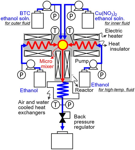
Figure 2. Detailed structure of the microstructured mixer: (a) overall structure; (b) vertical cross-section along the green line; (c) horizontal cross-section along the white line; (d) tip view of tube 2; (e) tip view of the rod; (f) upper end view of tube 3; and (g) lower end view of tube 3.
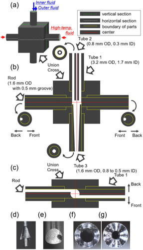
Table 1. Experimental conditions for continuous Cu-BTC synthesis.
Figure 3. X-ray diffraction patterns of the products synthesized using the microstructured mixer.
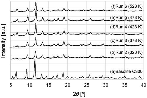
Figure 4. Product yield at each temperature.
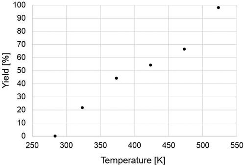
Figure 5. Average particle diameter and crystallite diameter of the products at each temperature.
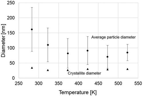
Figure 6. Typical SEM images of the products synthesized using the microstructured mixer.
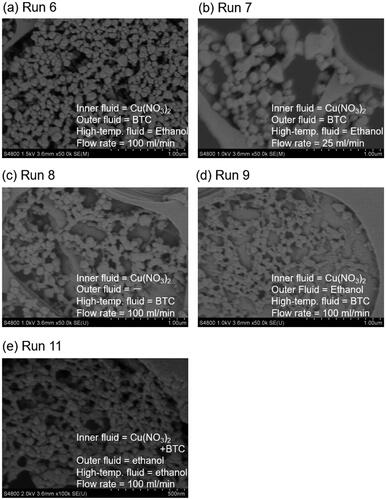
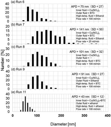
Figure 7. Particle diameter distribution of the products synthesized at 523 K.