818
Views
9
CrossRef citations to date
0
Altmetric
Articles

Development of safety injection flow map associated with target depressurization for effective severe accident management of OPR1000

, , , &
Pages 1502-1512 | Received 18 Jun 2015, Accepted 27 Nov 2015, Published online: 08 Jan 2016

Figures & data

Table 1. States of nuclear power plant recommended by IAEA [Citation1].

Figure 1. Flowchart of OPR1000 SAMG.

Figure 1. Flowchart of OPR1000 SAMG.

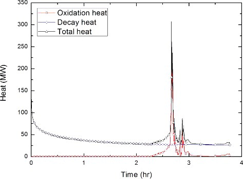
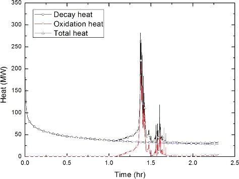
Table 2. A summary of severe accident analysis.

Figure 2. RCS SI flow map in OPR1000 SAMG.

Figure 2. RCS SI flow map in OPR1000 SAMG.

Figure 3. MELCOR nodalization for OPR1000.

Figure 3. MELCOR nodalization for OPR1000.

Figure 4. MELCOR nodalization for reactor core of OPR1000.

Figure 4. MELCOR nodalization for reactor core of OPR1000.

Table 3. Design value and steady-state condition of OPR1000.

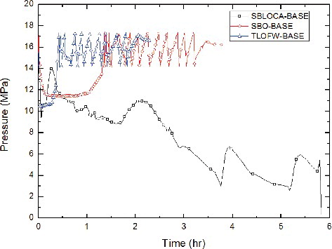
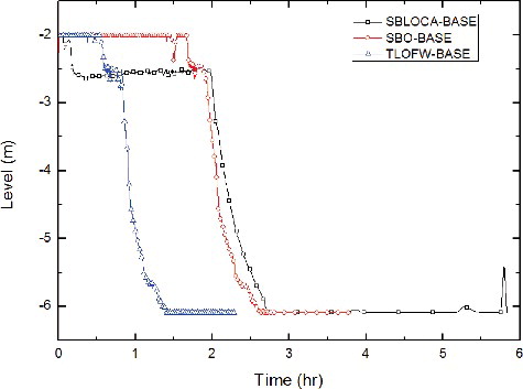
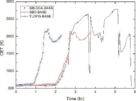
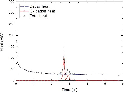
Table 4. Major accident sequences in the base case.

Figure 5. Behavior of reactor core water level with respect to CET for base cases.

Figure 5. Behavior of reactor core water level with respect to CET for base cases.

Figure 6. Behavior of RCS pressure for base cases.

Figure 6. Behavior of RCS pressure for base cases.

Figure 7. Behavior of reactor core water level for base cases.

Figure 7. Behavior of reactor core water level for base cases.

Figure 8. Behavior of CET for base cases.

Figure 8. Behavior of CET for base cases.

Figure 9. Oxidation and decay heat generation during SBLOCA scenario.

Figure 9. Oxidation and decay heat generation during SBLOCA scenario.

Figure 10. Oxidation and decay heat generation during SBO scenario.

Figure 10. Oxidation and decay heat generation during SBO scenario.

Figure 11. Oxidation and decay heat generation during TLOFW scenario.

Figure 11. Oxidation and decay heat generation during TLOFW scenario.

Figure 12. A simplified reactor pressure vessel for SI flow model.

Figure 12. A simplified reactor pressure vessel for SI flow model.

Figure 13. Characteristic pump curve by one and two HPSIs.

Figure 13. Characteristic pump curve by one and two HPSIs.

Figure 14. RCS SI flow map for SBLOCA scenario.

Figure 14. RCS SI flow map for SBLOCA scenario.

Figure 15. RCS SI flow map for SBO scenario.

Figure 15. RCS SI flow map for SBO scenario.

Figure 16. RCS SI flow map for TLOFW scenario.

Figure 16. RCS SI flow map for TLOFW scenario.

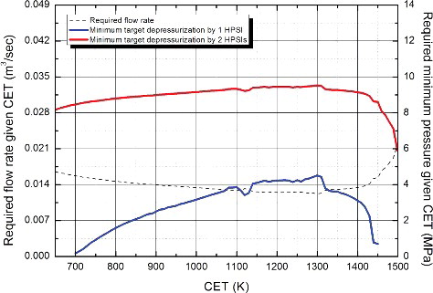
Table 5. The time of cladding melting and core recovery for the selected coolant injection.

Reprints and Corporate Permissions

Please note: Selecting permissions does not provide access to the full text of the article, please see our help page How do I view content?

To request a reprint or corporate permissions for this article, please click on the relevant link below:

Academic Permissions

Please note: Selecting permissions does not provide access to the full text of the article, please see our help page How do I view content?

Obtain permissions instantly via Rightslink by clicking on the button below:

If you are unable to obtain permissions via Rightslink, please complete and submit this Permissions form. For more information, please visit our Permissions help page.