
Figures & data
Figure 1. A, Tectonic setting of New Zealand. Green rectangle marks location of B. B, Location of the Taupo Rift (active faults in red from Langridge et al. Citation2016). Yellow rectangle marks location of C. C, Location map of the Mt Ruapehu Graben, Upper Waikato Stream (UWS), Wahianoa and Rangipo faults in the southern part of the Tongariro Volcanic Complex, in southern Taupo Rift. Potential intersection area marked with a purple rectangle (UWS).
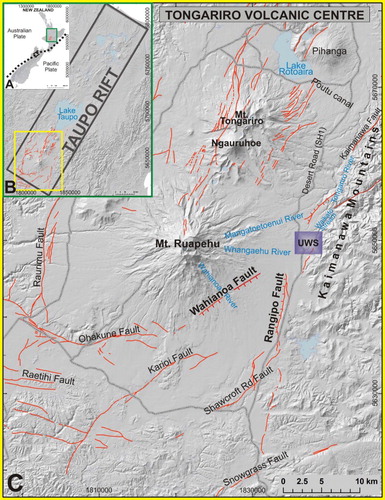
Figure 2. Chronological stratigraphic summary of the laharic and lava formations and andesitic tephras from the Tongariro Volcanic Centre interbedded with distal rhyolitic tephras from the Taupo Volcanic Zone calderas. Notice the general stratigraphic record for the Upper Waikato Stream and Wahianoa Fault areas at the right. *The oldest laharic formations’ ages are based on the Rotoehu ash age (45.16 cal ka BP; Danišík et al. Citation2012). Ru, Ruapehu; Tg, Tongariro; Ng, Ngāuruhoe; Tp, Taupo; Ok, Okataina, R# corresponds to the lahar episodes as described by Cronin & Neall (Citation1997).Citation Citation Citation Citation Citation Citation Citation Citation Citation Citation
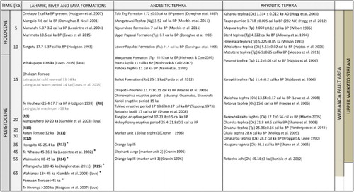
Figure 3. Geological map and general stratigraphy of the SE Mt Ruapehu area (after Townsend et al. Citation2008; Lee et al. Citation2011), showing the location of the study sites (sections 1–3) and active surface fault traces (Langridge et al. Citation2016). See for detailed stratigraphic record.
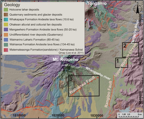
Table 1. Net-slip, single-event displacements, progressive displacements and timing of rupture of the Upper Waikato Stream Fault, at section 1.
Figure 4. Terrestrial laser scanning survey. A, Upper Waikato Stream (UWS) 3D point cloud data. B, Oblique view of the digital outcrop model of the wall ‘a’ in the Upper Waikato Stream Fault built with 3DReshaper Application. C, Satellite image (using Google Earth images, 2015) showing the scanning locations and river exposures (walls) for the terrestrial laser scanning survey in the Upper Waikato Stream, section 1 (see location on ).
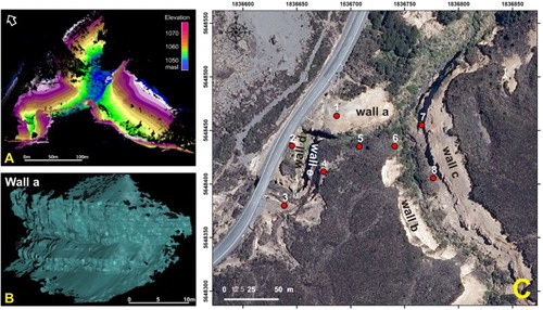
Figure 5. Location of the main faults in the Upper Waikato Stream area. A, Hillshade map of the Upper Waikato Stream based on 2 m DSM showing the studied faults in sections 1 (green rectangle) and 2 (blue dots, blue rectangle). Fault exposures (dots) and fault traces (continuous lines) are differentiated from the inferred faults (discontinuous lines). Faults downthrown to the NW are marked with red lines; faults downthrown to the SE are marked with yellow–brown lines. The fault planes are plotted in stereographic (lower hemisphere) projection and superimposed rose diagrams of fault strike frequency (right-hand rule). B, Section 1 of the Upper Waikato Stream (green rectangle in A) showing the seven main fault traces (purple dots), as well as an extensional fracture and two transects t1 and t2 (white lines) used to sum and calculate total offset for the Upper Waikato Stream Fault.
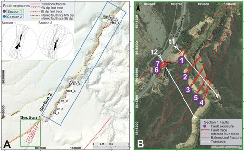
Figure 6. Faults in section 1 in the Upper Waikato Stream. A, Wall ‘a’ main fault exposure, showing fault 1 displacing volcanic deposits older than c. 28 ka (left, field photo; right, interpretation with stratigraphic column). B, Wall ‘b’ showing the location of fault 2 with a 0.3 m ‘fissure fill’ (left, field photo; right, interpretation with stratigraphic column). C, Detailed exposure of fault 4 on wall ‘b’ displacing tephras older than R11 lahars. The numbers show the elevation in m a.s.l. See for further information about stratigraphic units.
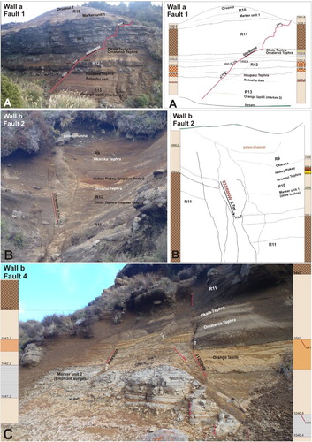
Figure 7. Extensional fractures located on wall ‘a’ in the Upper Waikato Stream. A, The 12 m long fissure filled with Ōruanui Tephra (white arrow; > 25.4 cal ka BP; photo taken by S. Donoghue), cutting older tephras and lahar deposits. B, Other fissures were measured on the same wall, cutting R11 lahars. C, These fissures do not show any vertical displacement, but record extension. D, The R11 lahar deposits are abruptly truncated at the fissure margins, with no mixed material along fissure sides. The reworked Ōruanui tephra shows cross-bedding stratified layers. E, All the fissures reflect orthogonal extension and are consistent with the NNE-trending Mt Ruapehu Graben. Rose diagrams for the measured fissures and faults in the Tongariro Volcanic Centre (TgVC), where strike directions (right-hand rule) are plotted.
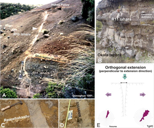
Figure 8. Main outcrops of the Upper Waikato Stream Fault in section 2. A, 10/4_2: Normal fault displacing the Papakai Formation. B, 10/4_3: Exposure of fault displacing deposits including R13 and older lahars.
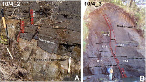
Table 2. Net-slip, single event displacement and timing of fault rupture of the Upper Waikato Stream Fault, at section 2.
Figure 9. Wahianoa Fault profiles and outcrops. A, Geological map (Leonard et al. Citation2014) showing the location of the studied field sites along the Wahianoa Fault in section 3; and the 10 topographic profiles (39)pehu. ld photo; B the TgVC (e) traced with their corresponding vertical offset values in metres. The geological map overlies a hillshade created with a 2 m-resolution Digital Surface Model from the SE flank of Mt Ruapehu. B–C, The two main outcrops of the Wahianoa Fault in section 3 showing displaced tephra (field locations shown on A). The fault planes are plotted in stereographic (lower hemisphere) projection and superimposed rose diagrams of fault strike frequency (right-hand rule). Most of the tephra belongs to the Bullot Formation from Mt Ruapehu (Donoghue & Neall Citation2001; Pardo et al. Citation2012). See for more information about the stratigraphy and for location of section 3.
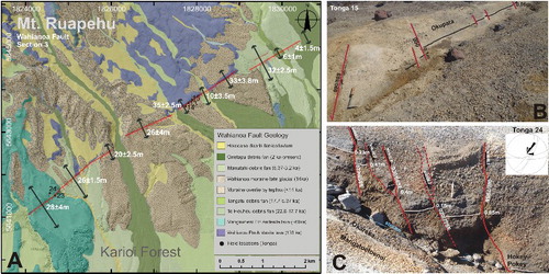
Table 3. Net-slip, single-event displacements, progressive displacements and timing of rupture of the Wahianoa Fault, at section 3.
Table 4. Comparison of fault rupture number and timing of the Upper Waikato Stream, Wahianoa and Rangipo faults.
Figure 10. Fault slip-rate variation from > 45 ka to present day for the Rangipo Fault (![]()
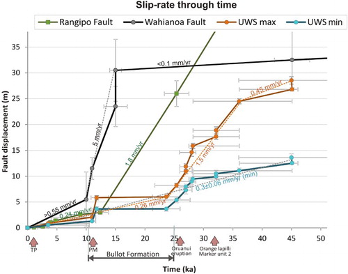
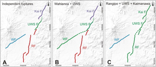
Figure 11. Potential physical intersections and rupture models of the Upper Waikato Stream Fault with Rangipo and Wahianoa faults. A, Independent ruptures. B, Potential rupture of the Wahianoa (WF) and Upper Waikato Stream (UWS F) faults (27 km). C, Potential rupture of the Rangipo (RF), Upper Waikato Stream and Kaimanawa (Kai F) faults (43 km).