
Figures & data
Figure 1. Location map with Riverton section field area boxed. Also shown are intrusive rocks of the Median Batholith, and the largely volcanic Brook Street Terrane (the western contact of the terrane is not exposed on this coast). Basement geology based on Turnbull and Allibone (Citation2003).
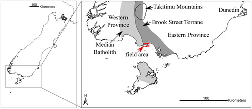
Figure 2. Lithofacies map and generalised vertical successions (GVS). Outcrop along the coast is almost continuous; inland it is sparse. Numbered circles mark field localities. Bold line on inset map shows the location of the cross-section (A) relative to mapped geology.
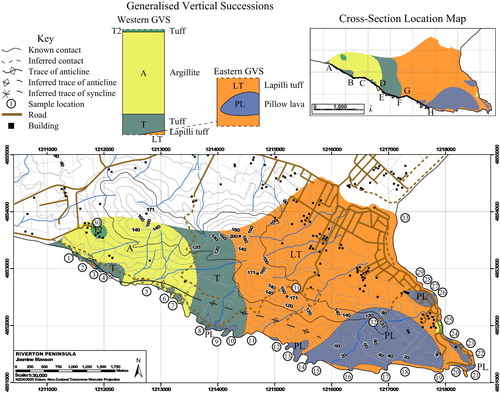
Figure 3. A, Cross-section along the coast, showing lateral relationships among lithofacies. This section is vertically exaggerated (×2) so relationships can be better seen. The strips of lapilli tuff in section E–F are a schematic representation of lapilli tuff filling channels in tuff (see text). Argillite and tuff are in part interbedded (not illustrated). B, Logged stratigraphic section of the western side of the sequence (that represented in the Western GVS of ).
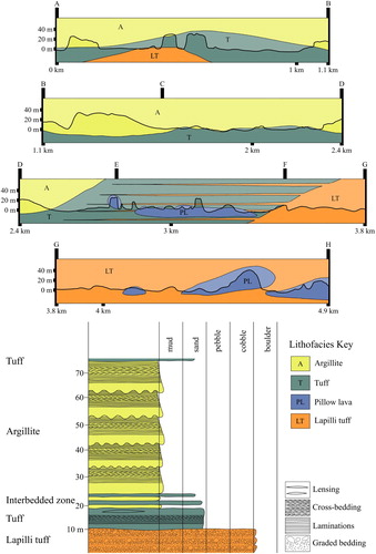
Figure 4. Features of these rocks include: A, Reverse-graded beds in lapilli tuff, with black arrows showing the direction of grading. B, Lapilli tuff filling channels within tuff; C, Peperitic contact between pillow lava below and tuff above. D, Argillite showing Bouma sequences (dotted lines denote boundaries between successive sequences; notebook for scale has 20 cm spine). E, Clasts in lapilli tuff at site 29, showing the distinction between aphyric clasts and those with abundant amygdales, with quartz cement in the matrix. F, Examples of clasts within the tuff, including those bearing chlorite-filled amygdales, and those with albite laths. G, Amygdale in pillow lava showing pumpellyite rim and mixed centre: regions with different crystal sizes are also visible. H, Dike, showing fresh clinopyroxene and altered plagioclase phenocrysts and chlorite pseudomorphing crystal shapes. Thin section images in plane polarised light.
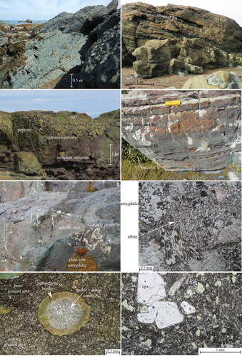
Table 1. Summary of lithofacies features.
Figure 5. Clinopyroxenes are mostly augite and diopside.
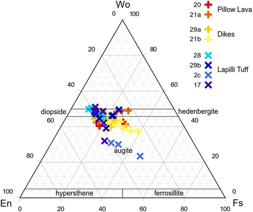
Figure 6. Measured feldspar compositions. End-member albite and orthoclase probably formed during alteration.
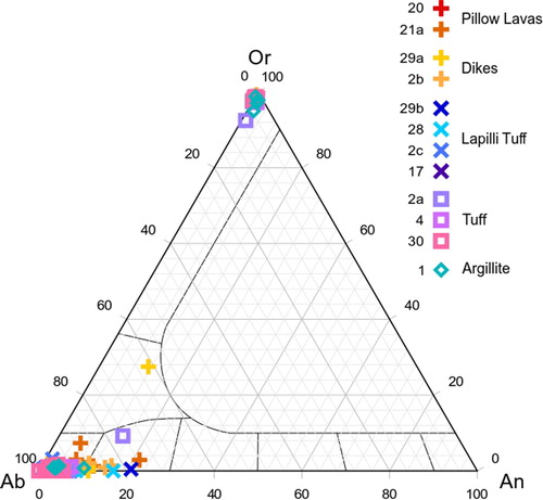
Figure 7. A, Chondrite-normalised rare earth element (REE) and B, Primitive mantle-normalised trace element profiles for the averages of the cores of augite crystals for each sample. Normalising values from Sun and McDonough (Citation1989).
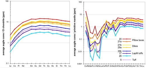
Figure 8. Calculated model whole-rock A, Chondrite-normalised rare earth element and B, Primitive mantle-normalised trace element profiles, compared to whole-rock data from Spandler et al. (Citation2005), showing similar patterns with a few notable differences (see text, Supplement). Normalising values from Sun and McDonough (Citation1989).
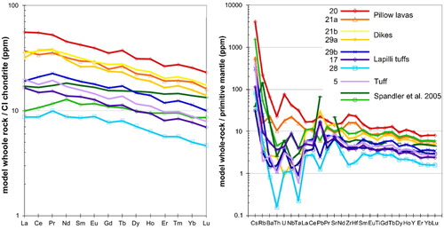
Figure 9. Plots of A, Y/Yb vs. Nb/Yb after Maurice et al. (Citation2012) and B, Ba/Yb vs. Nb/Yb after Pearce and Stern (Citation2006). Key in bottom right applies to both plots.
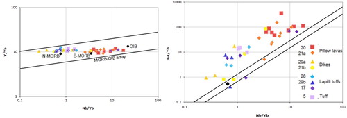
Figure 10. Map showing inferred volcanic depositional systems and positions of two small volcanic centres. Positions of depositional fan lobes and branching channel indicated by features in outcrop. Argillite is derived from the main volcano’s central vent(s); tuff and lapilli tuff from satellite vents form the marked lobes. Trace element sample numbers are marked on the map; positive Pb anomaly = oval symbols, negative Pb anomaly = rectangles.
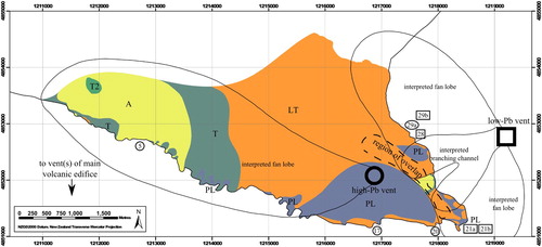
Figure 11. depositional system scenarios for the Riverton section (not to scale); A, Single lobe of a submarine fan, with lapilli tuff-filled channels. B, Large-scale lapilli tuff-filled channel with tuff turbidites forming levees.
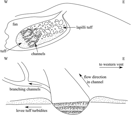
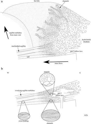
Figure 12. interpretative cross-section of the Riverton section along the Colac Bay coast, showing a proposed structure and sequence of events for deposits of the western vent (not to scale): A, Initial generation of pillow lava is accompanied by generation of hyaloclastite which is redeposited in a submarine fan lobe by a series of channel-forming mass flows. B, A second (observed) generation of pillow lava intrudes these deposits to form peperite.
Supplemental material
Download MS Word (693.4 KB)Data availability statement
The data that support the findings of this study are openly available in Pangaea https://doi.pangaea.de/10.1594/PANGAEA.917577, reference number PDI-23688.