
Figures & data
Figure 1. Topographic and tectonic settings of the broader environment of New Zealand (Zealandia) with respect to the locations of Cenozoic monogenetic volcanism; Auckland Volcanic Field (AVF) (inset A), South Auckland Volcanic Field (SAVF) and Waikato coastline (W) (inset B), Taupo Volcanic Zone (TVZ) (inset C) and Central and East Otago with Waipiata Volcanic Field (WVF) and Dunedin Volcanic Complex (inset D). Bathymetric information of offshore Zealandia was derived from the 250 m resolution gridded bathymetric data (2016), National Institute of Water and Atmospheric Research (NIWA) (Mitchell et al. Citation2012). Tectonic and structural information from Mortimer et al. (Citation2017). Regional maps of the TVZ, South Auckland and Waikato region and the central Otago region were plotted to the 8 m NZ DEM (LINZ – Land Information New Zealand Citation2012), whereas the Auckland Volcanic Field was mapped on a 1 m LiDAR DEM (LINZ – Land Information New Zealand Citation2013).
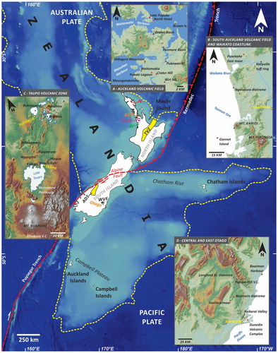
Figure 2. A – Pukekohe East maar (PEM) from the air (South Auckland Volcanic Field), Note the flat crater floor and the smooth surface of the tephra ring surround the maar crater; B – Overview of the Motukorea/Brown Island (Auckland Volcanic Field) complex tuff ring (tr). Note the scoria cone (sc) complex filling the crater of the tuff ring.; C – Overview of the Maungauika/North Head tuff cone (Auckland Volcanic Field) from the east. The core of the tuff cone (tc) is preserved, its outer edifice has been shoaled away. The centre of the tuff cone is filled with a scoria cone (sc); D – Overview or the preserved part of the Foulden Maar (Waipiata Volcanic Field). The image was taken from the north. Small quarry operation of diatomite is in the middle of the depression (red arrow). In the left side of the view an erosional remnant of a scoria cone (Bald Hill) sitting on the tuff ring.
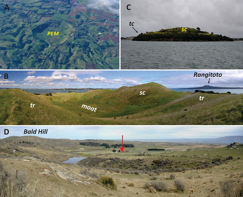
Figure 3. A – A small diatreme is exhumed as the base of the Punatekahi volcanic complex (Taupo Volcanic Zone). Note the v-shaped architecture of pyroclastic rocks in the base of the section (white dashed lines), marking an exposed diatreme (d).; B – Te Hukui Basalt formation exposing typical phreatomagmatic pyroclastic successions in a well-defined small area inferred to be a diatreme near the Puketerata Volcanic Complex, Taupo Volcanic Zone (note people for scale); C – pyroclastic rocks recovered from the Punatekahi diatreme is composed of glassy juvenile ash and lapilli and abundant accidental lithic clasts forming a bedded, cross-bedded succession inferred to accumulated by base surges; D – Accretionary lapilli-bearing basaltic lapilli tuff and tuff succession from the middle section of the Te Hukui diatreme.
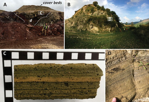
Figure 4. A – Overview of the Ngatatura diatreme (d) from the NW located along the Waikato coastline (D). Note the steep diatreme wall (white dashed lines) that slightly enlarged upsection. The cliff face is about 60 m high; B – Close up view of the pyroclastic breccia of the Ngatatura diatreme rich in angular glassy juvenile pyroclasts (j) and variable rounded sedimentary (s) rocks from the pre-volcanic deposits; C – Over the Ngatatura diatreme shallow marine sediments (ms) intercalated with a hyaloclastite breccia (hy) suggesting a younger eruptive phase in the same area where the diatreme formed previously.
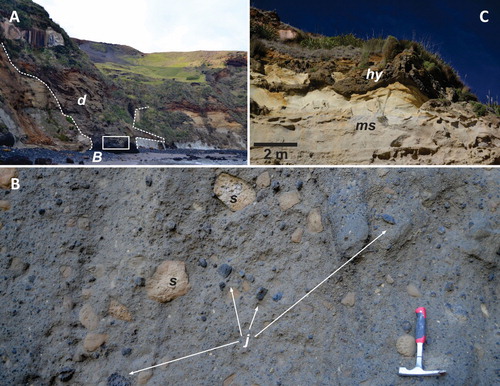
Figure 5. A – Half section of a Surtseyan tuff cone along the Waikato coastline, just south of Karioi Mountain. Note the strong erosional features, u-shaped channels (u), and the dune-bedded pyroclastic succession typical for an emergent volcano, commonly defined as a result of Surtseyan style eruptions (hammer is for scale); B – Various distal beds of eruption fed density currents at Boatman Harbour in Oamaru as part of a complex emergent volcano. Soft sediment deformation (ss) features are apparent; C – Half section of a Surtseyan volcano with thick pyroclastic succession (pyx) at Cape Yoiung, Chatham Island intruded by feeder dykes with peperitic margin (d), section is about 70 m high; D – Lower sequence of the pyroclastic succession of the Maungaika/North Head Surtseyan volcano at the Auckland Volcanic Field.
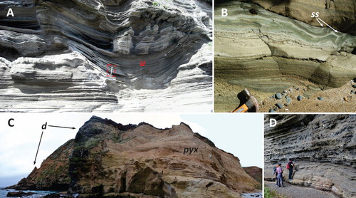
Figure 6. A – Overview of the half section pyroclastic succession of an emergent volcano (Kaiapo) near the city of Taupo, Taupo Volcanic Zone (hammer is for scale). Arrows indicate coarse-grained juvenile pyroclast-rich layers; B – Lapilli tuff from the middle section of the pyroclastic succession of the Kaiapo volcano. Larger angular juvenile, low-vesicularity pyroclasts arrowed with white. Some orange-brown coloured pyroclasts are juvenile palagonitized pyroclasts (yellow arrows); C – Pyroclastic succession of the Ohakune Volcanic Complex exposes alternating magmatic explosive (m) and phreatomagmatic explosive (ph) pyroclastic deposits (Taupo Volcanic Zone); D – Fine grained tuff of phreatomagmatic origin at Ohakune Volcanic Complex basal section with vertical pipes (arrows).
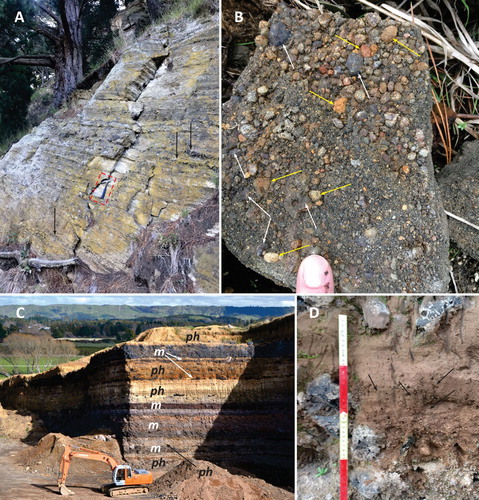
Figure 7. A – Pyroclastic breccia rich in accidental lithic fragments from an exhumed diatreme near Longland Station, Swinburn Plateau (Waipiata Volcanic Field). View is about 20 cm across; B – Base surge units of the Pigroot Hill Volcanic Complex along the Red Cutting Summit (Waipiata Volcanic Field). Camera bag is for scale (12 cm long); C – Ballistic bomb (arrow shows impact direction) causing impact sag on the phreatomagmatic pyroclastic successions of Motukorea/Browns Island (Auckland Volcanic Field). Pen is 14 cm long; D – Cauliflower-shaped bombs (arrows show impact directions) from the basal section of the Orakei Basin maar (Auckland Volcanic Field). Arrows point to the impact direction (50c coin is for scale).

Figure 8. A – Dune-bedded base surge deposits in the mid-section of the Motukorea/Browns Island tuff ring (Auckland Volcanic Field). Arrow shows transport direction, hammer is for scale; B – Climbing dunes of a base surge succession in the upper section of the tuff ring of the Lake Pupuke maar pyroclastic deposits, Auckland Volcanic Field (Arrow shows transport direction); C – Weathered, palagonitized dune bedded phreatomagmatic tuff from a tuff ring of Pukewairiki/Highbrook Park (Auckland Volcanic Field) (Arrow shows transport direction); D – Weathered accretionary lapilli-rich phreatomagmatic tuff from the southern crater rim of Pukekohe East maar (South Auckland Volcanic Field)
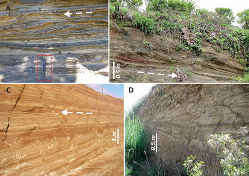
Figure 9. A – Nearly a metre thick scoriaceous bed (s) in the middle of the phreatomagmatic succession of Motukorea/Browns Island tuff ring indicates intermittent changes in the eruption style during the edifice growth of the tuff ring (Auckland Volcanic Field). Note the normal fault that dissect the section (arrows); B – The Motukorea/Browns Island tuff ring is capped by a thick scoriaceous lapilli and agglomeratic unit (white dashed line) indicating the complete eruption style changes to magmatic explosive in the end of the volcanic activity. Note the scoria cone (sc) in the background filling the crater of the tuff ring (tr); C – Well-exposed section at Te Manurewa o Tamapahore/Wiri Mt tuff ring (Auckland Volcanic Field) showing a capping magmatic succession (m) over the phreatomagmatic pyroclastic units (ph); D – Complex magmatic capping unit at Te Manurewa o Tamapahore/Wiri Mt showing gradual eruption style changes and the growth of a complex lava spatter and scoria cone intercalated with clastogenic lava flows (s1-s2-s3) and the entire section covered by lava flows (lf).
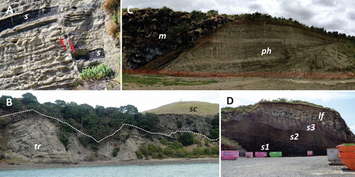
Figure 10. A – SEM image of an interactive particle, a glassy pyroclasts with fractured texture and blocky, non-vesicular appearance indicating MFCI process to be responsible for its formation; B – Close up view of a glassy pyroclasts from Orakei Basin maar showing surface textural features (arrows) suggest brittle fragmentation caused by magma-water explosive interaction; C – Thin section view (plane parallel light) of an accretionary lapilli (ac) from a fine grained tuff of the Crater Hill tuff ring succession. The image is about 1 mm across; D – A peperitic domain as a lapilli in the basal tuff ring sequence of the Mangere Mountain (Auckland Volcanic Field)
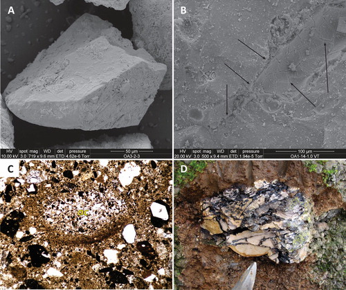
Figure 11. A – Slightly palagonitized sideromelane pyroclast in thin section (plane parallel light) from the ejecta ring of the Pukaki Lagoon maar, Auckland Volcanic Field. Note that the pyroclasts has low vesicularity, it is blocky and has abundant microlites. The core of the pyroclasts (bounded by white dashed line) is still fresh while the outer part (o) became dark yellow indicating gradual palagonitization. The image is about 0.5 mm across; B – Tachylite (black) and sideromelane (yellow) glass in thin section (plane paralell light) from the tuff ring of Crater Hill (Auckland Volcanic Field). Note the palagonitization on the sideromelane glass shard in form of colour changes as well as the thin rim around large pyroclasts forming armoured pyroclasts (arrows). The image is about 2 mm across.
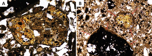
Figure 12. A – Typical proximal pyroclastic succession of a phreatomagmatic volcano in the Auckland Volcanic Field. The image was taken from the Waitomokia/Mt Gabriel tuff ring basal section. It is rich in shallow excavated accidental lithic clasts commonly forming distinct bomb horizons (arrows) that can be interpreted as ballistic curtain deposits; B – A typical sieved sample from the fine tuff beds of the Panmure Basin maar ejecta ring succession. The image shows the 125–250 μm size fractions. The grains are mineral phases (mostly quartz) derived from various siliciclastic country rocks that have been ‘recycled’ by the phreatomagmatic explosions and crater excavation. Note the dark volcanic glass shards; C – Sedimentary rock fragment (s) in a cored basaltic bomb from the basal succession of the ejecta ring of the Orakei Basin maar (Auckland Volcanic Field); D – Thin section image of a pyroclastic rock from the Nenthorn Diatreme (Waipiata Volcanic Field). The samples contain abundant glauconite (g) from pre-volcanic marine sediments that were eroded away in the region. The identification of such grains used as proof to state that marine sedimentary cover existed in the region in the time the maar-diatreme formed.
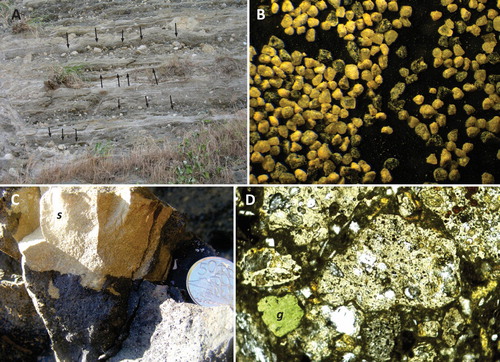
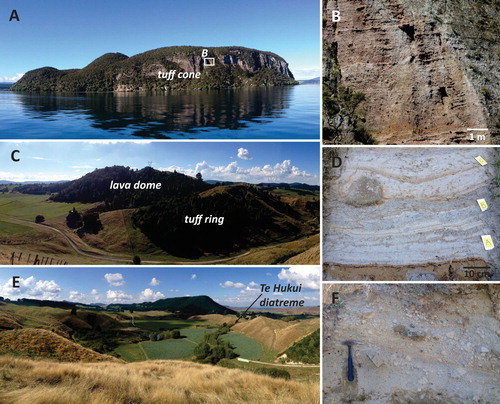
Figure 13. A – View of the exposed, more than 100 m thick pyroclastic succession of Motuoapa Peninsula from Lake Taupo; B – Coarse PDC and fall-dominated sequence of the middle upper succession of Motuoapa pyroclastic deposits; C – Larger dome of Puketerata Volcanic Complex, which surrounded by an atypical steep-sided tuff ring; D – Wet surge-dominated cohesive layers with a bomb sag of large rhyolitic clast and thin better sorted shower-bedded layers at the base of the Puketerata sequence; E – Chain of maar craters relating to the NE section of the Puketerata fissure eruption. The arrow indicates the location of the Te Hukui diatreme (B); F – Block-and-ash-flow deposits found near the top of the western side of the ejecta ring that surrounds the larger dome.
Data availability statement
Data sharing is not applicable to this article as no new data were created or analyzed in this study.