Figures & data
Fig. 1. Isometric rendering of the TREAT reactor.Citation13
Fig. 2. (a) SAT vehicle and (b) STEP vehicle schematic.Citation17
Fig. 3. (a) Sectional view of MARCH system assembly, (b) SETH capsule, and (c) M-SERTTA module.Citation18
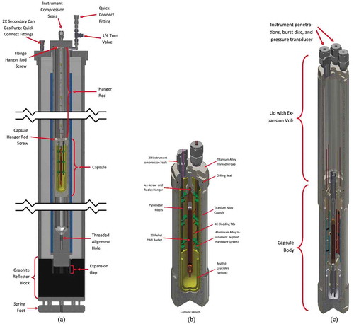
Fig. 4. (a) Picture of TRTL and (b) rendering of TRTL primary loop.
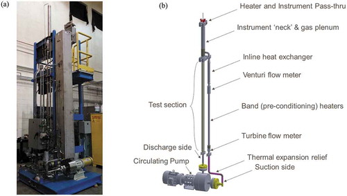
TABLE I Engineering Requirements for Operational Envelope
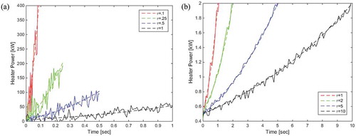
Fig. 5. General phenomenological mechanisms and respective time constants for HSN versus HI (CitationRef. 30).
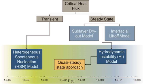
Fig. 6. (a) Isometric cut view and (b) isometric cut breakouts of TRTL primary loop.
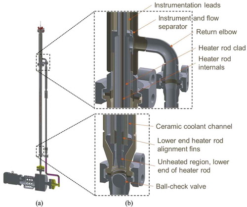
Fig. 7. Local pressure losses computed across the TRTL test section.
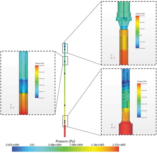
TABLE II Instrumentation Plan and Respective Alignment with FOMs
Fig. 8. (a) Schematic for the TRTL pressure and (b) temperature sensor arrangement [DP = differential pressure measurement, PT = gage-pressure measurement, FIT = volumetric flow measurement, TF = temperature measurement of fluid, and TW = temperature measurement at a wall (outer clad temperature).]
![Fig. 8. (a) Schematic for the TRTL pressure and (b) temperature sensor arrangement [DP = differential pressure measurement, PT = gage-pressure measurement, FIT = volumetric flow measurement, TF = temperature measurement of fluid, and TW = temperature measurement at a wall (outer clad temperature).]](/cms/asset/364c3143-0937-46d1-8100-8fd30b3b0aff/unct_a_1720559_f0008_oc.jpg)
Fig. 9. Placement of pressure tube and thermocouple in the flow channel.
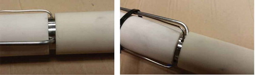
Fig. 10. High-powered heater rod with thermocouple sheath.
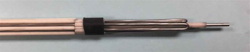
Fig. 11. Arrangement of pressure tube and thermocouples for test section.
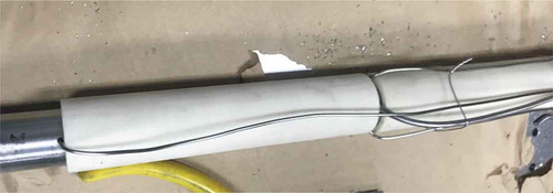
Fig. 12. Flow and differential pressure measurement assessment.
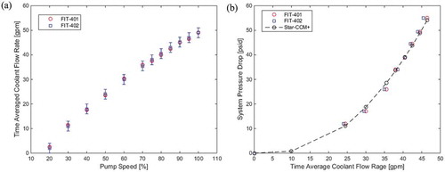
Fig. 13. System pressure measurement assessment.
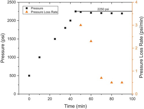
Fig. 14. Temperature measurement assessment.
Fig. 15. Linear heat generation rate measurement assessment.