
Figures & data
TABLE I Main Characteristics of the As-Manufactured Fuel Rods
Fig. 1. Power histories and axial power profiles during the xM3 base irradiation and power ramp.
TABLE II Main Characteristics of the Simulated Power Ramps
Fig. 2. Power histories and axial power profiles during the HBC4 base irradiation and power ramp.
Fig. 3. Transverse cross section of the unfailed xM3 rod after the power ramp.
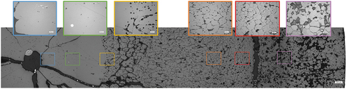
Fig. 4. Rod diameter profile after the HBC4 power ramp with the location of the transverse (CT) and longitudinal (CL) cross sections and of the central holes.
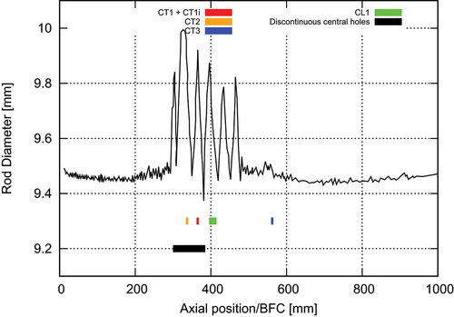
Fig. 5. HBC4 rodlet. Transverse cross section CT1. Clad failure is visible on the right side.
Fig. 6. HBC4 rodlet. Transverse cross section CT1’, obtained by grinding and polishing downward CT1.
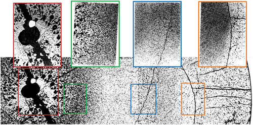
Fig. 7. HBC4 rodlet. Transverse cross section CT2.
Fig. 8. HBC4 rodlet. Longitudinal cross section CL1.
TABLE III Melting Fuel Radii Based on the Available xM3 and HBC4 Cross Sections
Fig. 9. Calculated clad diameters and pellet-clad gaps at the end of xM3 and HBC4 base irradiations compared to available measurements.
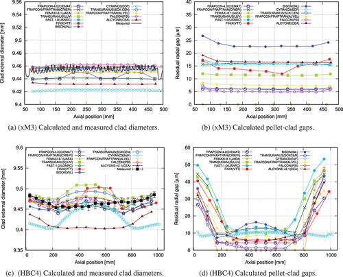
Fig. 10. Calculated fuel centerline temperature evolution at PPN during the xM3 power ramp.
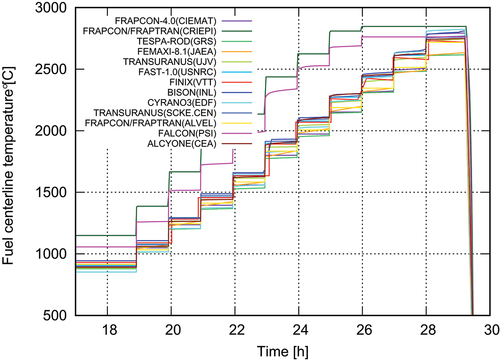
Fig. 11. Calculated axial profiles of the fuel centerline temperature at RTL, calculations at nominal power.
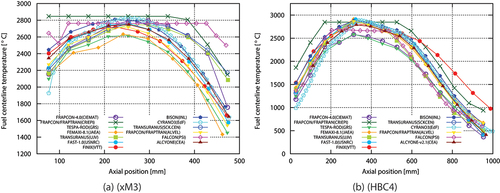
Fig. 12. Calculated and measured residual strain, pellet diameter, and gap axial profiles at the end of the xM3 power ramp.
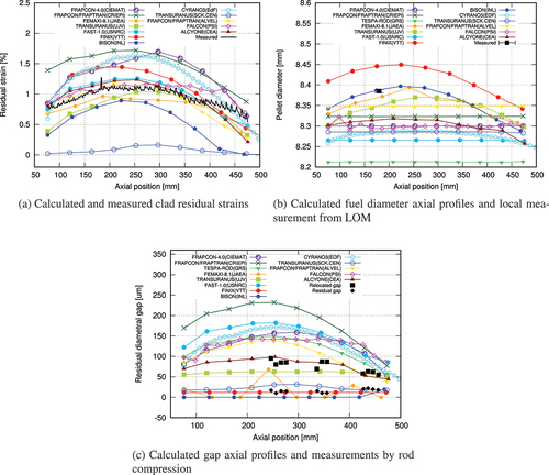
Fig. 13. Calculated and measured rod elongations during the xM3 ramp (the results are normalized with respect to the clad length at the end of the conditioning plateau).
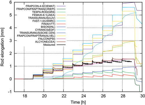
Fig. 14. Calculated and measured clad axial profiles after the HBC4 power ramp.
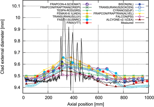
Fig. 15. Calculated and measured FGR after the xM3 power ramp.
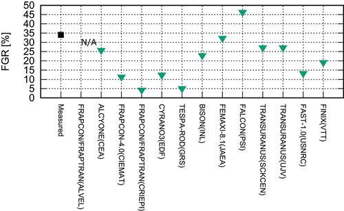
Fig. 16. Axial profiles of calculated melting radii at RTL compared to measurements.
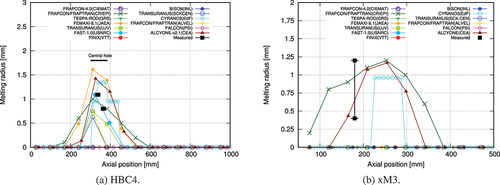
Fig. 17. Calculated melting fuel melting radii and centerline temperatures at PPN and RTL in the simulations of xM3 (power uncertainty 5%) and HBC4 (power uncertainty
7%).
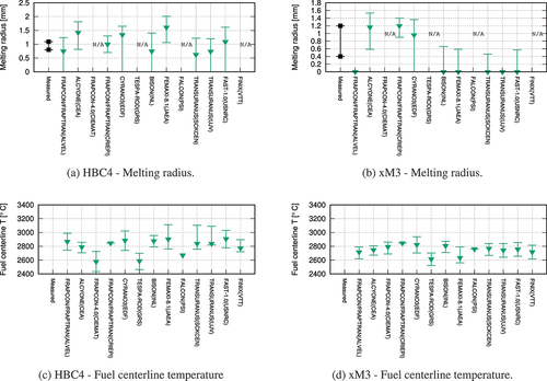
Fig. A.1 Setup for the gap measurements.
TABLE B.I Main Models and Criteria in the Codes
TABLE B.II Main Models for Fuel Melting in the Codes*