Figures & data
Figure 1. (a) Schematic representation of the 'worst case' of a realistic particle-particle contact with a surface oxide layer partially cracked in the contact zone and the current flowing through conducting spots formed along these cracks. (b) Sophisticated model-system describing volumetric electric heating of the material around a small conductive zone where the current is forced through between two electrically insulated semi-infinite bodies. (c) Simplified model with a circular heat source representing the Joule heat inside an infinite body.
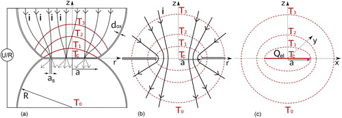
Figure 2. Temperature in the particle contact area normalised by the maximal contact temperature in the stationary state displayed as function of τ that includes material parameters and contact radius (). The experimentally verified models developed for volumetric heating by a current passing through the contact spot [Citation11,Citation17] show a satisfying accuracy of the simplified model used in the present publication.
![Figure 2. Temperature in the particle contact area normalised by the maximal contact temperature in the stationary state displayed as function of τ that includes material parameters and contact radius (τ=λ/(ρa2) t). The experimentally verified models developed for volumetric heating by a current passing through the contact spot [Citation11,Citation17] show a satisfying accuracy of the simplified model used in the present publication.](/cms/asset/89eef99e-d10b-4004-b47b-63b009e0fe7a/ypom_a_1829349_f0002_oc.jpg)
Table 1. Time in milliseconds until 90% of the stationary contact-temperature is reached ( ) for copper, martensitic, and austenitic steel.
Figure 3. Schematic representation of the temperature evolution in the contact zone between two particles (black) as well as in the centre of the particle (red) during heating by a pulsed electric current. After an instationary phase when only the particle contacts are heated up (1) the generation of heat in the contact and its dissipation become equal (2, stationary phase). Still the centre of the particle is only slightly heated by the low current density passing through it. As soon as the heat front reaches the centre, the whole particle is heated up more or less equally (3, it deviates from being equally heated only because of the temperature dependent material parameters). When the current is turned of, the temperature in the contact zone rapidly decreases (4) until the whole particle will have a uniform temperature distribution, cooling slowly by heat loss through the electrodes or radiation from the surface of the die (5).
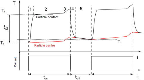
Figure 4. Supertemperature for different materials as a function of the current flowing through each particle-particle contact. The top scale shows approximately the currents through a powder compact of 15 mm diameter as well as the current density. The vertical lines indicate, for the same sample size, (i) the current through the specimen corresponding to the densification of copper at C when 40% of the total current of 320 A flow through the specimen [Citation10]), and (ii) the limit of the machine when all the current is assumed to flow through the sample (5000 A, thick red line). The different current assisted techniques (i) spark plasma sintering, (ii) flash spark plasma sintering (FSPS), (iii) electro-resistive sintering (ERS) and (iv) capacitor discharge compaction (CD) are given indicating the current density used for these processes. It can be seen that contact melting can be achieved for high current ERS or CD only. Note that the values are calculated for temperature independent material parameters. They will increase much faster than shown for higher supertemperatures (
K) and negative temperature coefficient of the resistivity.
![Figure 4. Supertemperature for different materials as a function of the current flowing through each particle-particle contact. The top scale shows approximately the currents through a powder compact of 15 mm diameter as well as the current density. The vertical lines indicate, for the same sample size, (i) the current through the specimen corresponding to the densification of copper at 600∘C when 40% of the total current of 320 A flow through the specimen [Citation10]), and (ii) the limit of the machine when all the current is assumed to flow through the sample (5000 A, thick red line). The different current assisted techniques (i) spark plasma sintering, (ii) flash spark plasma sintering (FSPS), (iii) electro-resistive sintering (ERS) and (iv) capacitor discharge compaction (CD) are given indicating the current density used for these processes. It can be seen that contact melting can be achieved for high current ERS or CD only. Note that the values are calculated for temperature independent material parameters. They will increase much faster than shown for higher supertemperatures (>100 K) and negative temperature coefficient of the resistivity.](/cms/asset/88e7c0ab-da8f-4e63-9734-d90a80f75e2c/ypom_a_1829349_f0004_oc.jpg)
Table 2. Temperature dependent material properties for pure copper (top) and 304 stainless steel (bottom).
Figure 5. Impact of changing particle radius on the supertemperature. The total current is fixed but the current through each contact changes while the current density is constant. Results from FE simulations marked with X are shown for comparison. The very high current density matches a custom-made lab-scale SPS apparatus used for the corresponding experiments [Citation20]). These results deviate by a factor of two from the calculated results using Equation (Equation4(4)
(4) ).
![Figure 5. Impact of changing particle radius on the supertemperature. The total current is fixed but the current through each contact changes while the current density is constant. Results from FE simulations marked with X are shown for comparison. The very high current density matches a custom-made lab-scale SPS apparatus used for the corresponding experiments [Citation20]). These results deviate by a factor of two from the calculated results using Equation (Equation4(4) ΔT=RcIc2πaλ.(4) ).](/cms/asset/a80a38ca-aa01-4585-a7b6-732c0cda144f/ypom_a_1829349_f0005_oc.jpg)
Figure 6. Impact of growing contact radius (densification) on the supertemperature. The total current as well as the current through each contact is fixed while the current density in the contact decreases.
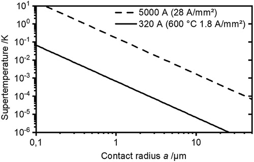
Figure 7. Dimension in the two-particle model to calculate densification rates. Densification is expressed as the approach of the particle centres. To reduce their distance l by , the Volume
has to be removed from the contact. As the material is moved to the neck surface, the contact radius grows from
to a.
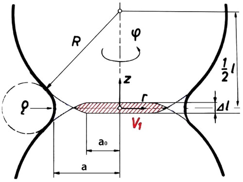
Table 3. Formulas to calculate the densification rate for different cases of material transport under the assumption, every atom is moved in a way that it leads to densification. The densification rate for pressure assisted diffusion along the grain boundary differs by a factor of 1.3 to 2 compared to Coble's solution [Citation47], if the simplifications , , and xdx = 2Rdl are used.
Figure 8. Densification rates calculated using the experimentally determined current through the powder compact of 128 A, as well as the assumption, the current can be changed to 5000 and 100000 A without varying the sintering temperature. The temperature gradients are obtained from the analytical solution given in Section 2 as . Temperature gradients along z for copper particles with
μm and
are
K/m, 300 K/m, and 115300 K/m, for 128 A, 5000 A, and 100000 A, respectively.
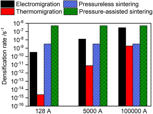
Table 4. Temperature independent material properties or such without information on temperature dependence; steel values for martensitic 1.4034, in brackets for pure α -iron, with index for γ -iron, with index for austenitic 1.4301. Coefficient of diffusion: .
Figure 9. Two-particle model with material flow routes in axial (∇z) and radial direction (through the grain boundary (∇r) and through the adjacent lattice (∇rr)) as well as along the particles surface (∇s).
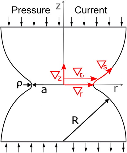
Figure 10. Temperature, temperature gradient and radial component of the electric field along different paths (c.f. Figure ) from FE simulations using a current of 280 A from model SPS experiments; MPa,
μm copper particles heated with 11500 K/s to
. The relative neck radius is
.
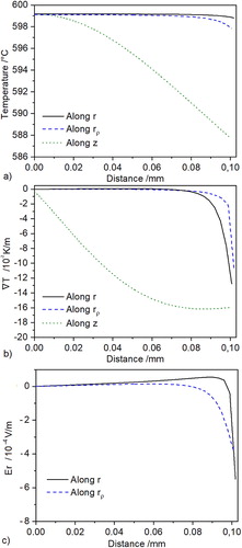
Table 5. Temperature gradients , radial component of the electric field and resulting densification rates for m copper powder after heating to C with a total current of 320 A. Values for a relative neck size of in pressing direction. With % of the theoretical density, the current is assumed to flow through 18140 parallel particles.
Table 6. Equations used to calculate the densification rate with the driving forces obtained from FE simulations given in Table .
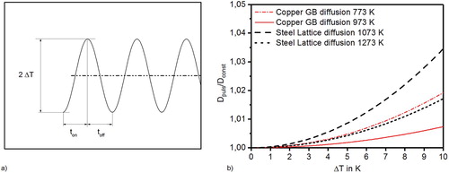
Figure 11. (a) Schematic representation of fluctuating temperature due to the pulsed current and (b) impact of pulsed temperature on the effective diffusion coefficient.