Figures & data
Figure 3. Cavity liquid fraction (CLF) as a function of dimensionless time (Fo) for various time steps (a) and grid sizes (b).
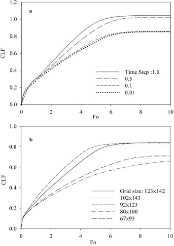
Figure 4. Numerical code validation of the present study with the numerical results of Brent, Voller, and Reid [Citation19], and the experimental study of Gau and Viskanta [Citation13].
![Figure 4. Numerical code validation of the present study with the numerical results of Brent, Voller, and Reid [Citation19], and the experimental study of Gau and Viskanta [Citation13].](/cms/asset/115d1bc9-1f1e-4be4-b347-1d5dd1f1815b/uhte_a_1404821_f0004_b.gif)
Table 1. Thermophysical properties of gallium and other non-dimensional parameters used in this study.
Figure 5. Streamlines at three different dimensionless times (Fo) for various Rayleigh numbers (Ra) and Ha = 0.
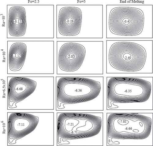
Figure 6. Isotherms at three different dimensionless times (Fo) for various Rayleigh numbers (Ra) and Ha = 0.
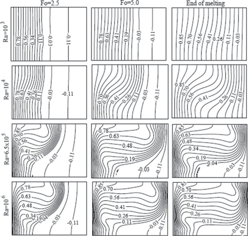
Figure 7. The solid–liquid phase interface at three different dimensionless times (Fo) for various Rayleigh numbers (Ra) and Ha = 0.
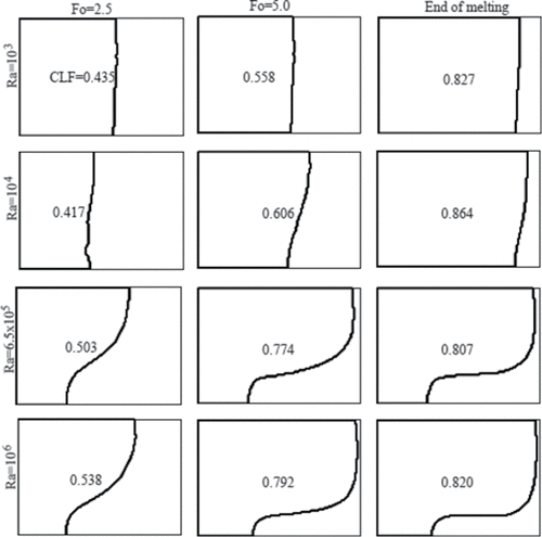
Figure 8. Evolution of the CLF in dimensionless time (Fo) for various Rayleigh numbers (Ra) and Ha = 0.
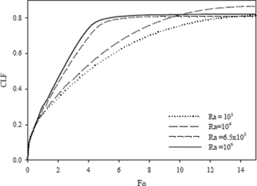
Table 2. The dimensionless time (Fo) for approaching steady state, and the corresponding cavity liquid fraction for various Rayleigh numbers (Ra).
Figure 9. Average Nusselt number at the hot wall as a function of dimensionless time (Fo) for different Rayleigh numbers (Ra) and Ha = 0.
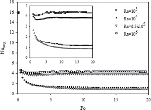
Figure 10. Streamlines at three different dimensionless times (Fo) for various Hartmann numbers (Ha) and Ra = 6.5 × 10⁵.
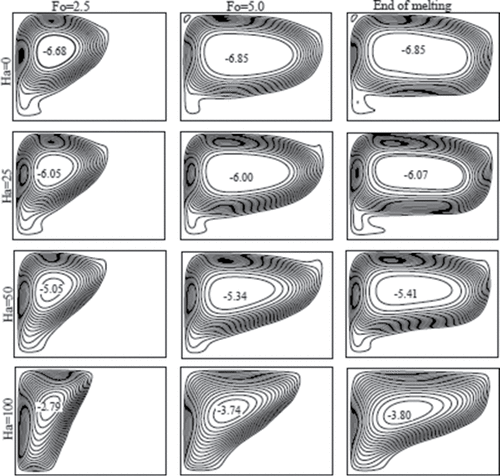
Figure 11. Isotherms at three different dimensionless times (Fo) for various Hartmann numbers (Ha) at Ra = 6.5 × 10⁵.
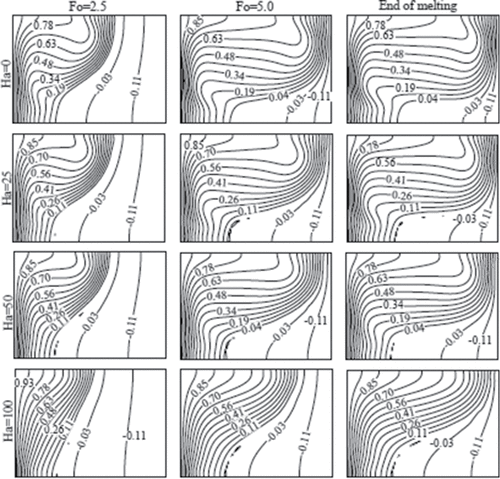
Figure 12. Solid–liquid interface at three different dimensionless times (Fo) for various Hartmann numbers (Ha) and Ra = 6.5 × 10⁵.
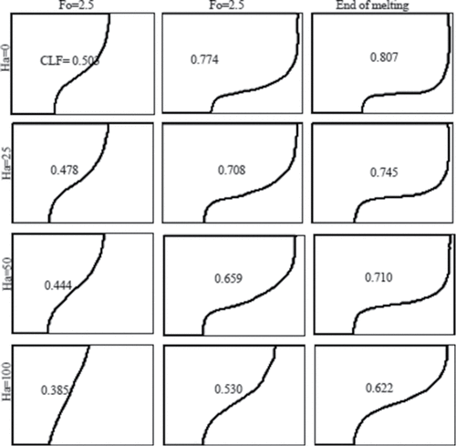
Figure 13. Evolution of the CLF in dimensionless time (Fo) for different Hartmann numbers (Ha) and Ra = 6.5 × 10⁵.
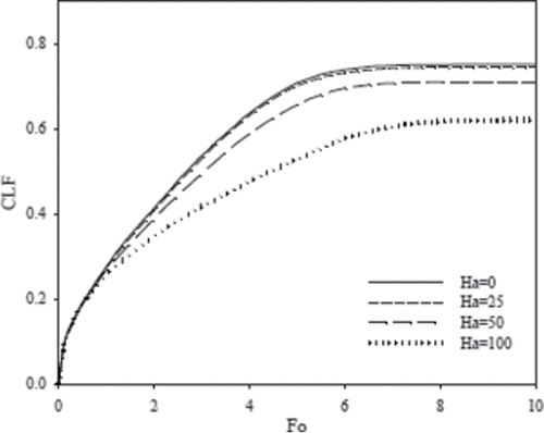
Table 3. The dimensionless time (Fo) for approaching steady state, and the corresponding cavity liquid fraction for various Hartmann numbers (Ha). The Rayleigh number in all these cases is Ra = 6.5 × 10⁵.
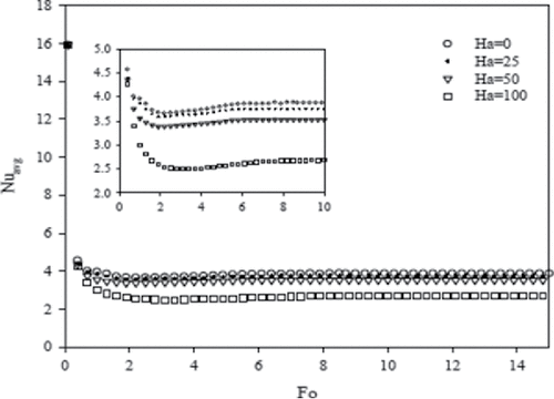
Figure 14. Average Nusselt number at the hot wall versus dimensionless times (Fo) for different Hartmann numbers (Ha) and Ra = 6.5 × 10⁵.
