Figures & data
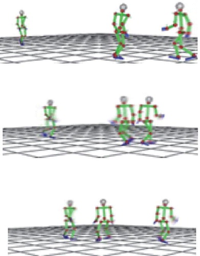
Figure 1. Overview of interaction primitives. Observation vectors are encoded into an HMM, which represents an interaction primitive.
Figure 2. Overview of recursive framework. A robot recursively predicts the partner’s behavior and decides its own subsequent actions using interaction primitives.
Figure 3. The state vector consists of three different vectors representing the velocity of the trunk, the joint angles of the whole body, and the relative position of the other.
Figure 4. Markers are attached to two performers. The positions of these markers are acquired by an optical motion capture system when the performers walk past each other. After this, the positions are converted into state vectors which represent interactions.
Figure 5. In case 1, one robot and two other agents are moving in the same space. The robot identifies the target agent, observes the target’s behavior, and synthesizes its own motion sequence using acquired interaction primitives represented by HMMs. The agents are programmed to move straight. The robot moves among two other agents without colliding with them. In case 2, two robots move in the same space and respond to each other’s actions. One robot swerves to the right and the other swerves to the left. These behaviors result in the collision of the two robots.
Figure 6. Five trajectories are displayed in case 1. The trajectories indicated by blue, red, and green circles represent the paths of the robot (A) and the two agents (B and C), respectively. The trajectories indicated by red and green solid circles represent the predicted paths of agents (B) and (C), respectively. Four trajectories are displayed in case 2. The trajectories indicated by blue and red circles represent the paths of robots (A) and (B), respectively, and the trajectories indicated by blue and red solid circles represent the predicted paths of robots (A) and (B), respectively.
Table 1. Results of movement pattern generation for each level: The number in each cell is the HMM number that generates the robot’s movement pattern. The number in parentheses is the HMM number that is searched to predict the partner’s motion. ‘s’ indicates straight motion.
Figure 7. Four pairs of recursive levels in two robots were tested in the interaction experiment. The upper left panel shows the paths of two robots, both of which use the 0th level of the recursive processes. These two robots move straight and collide with each other. The upper right panel shows the paths of robot (A) with the first level of the recursive process and robot (B) with the 0th level. Robot (A) swerves to the left and avoids collision with robot (B). The lower left panel shows the paths of the robots using the first level of the recursive process, where robot (A) swerves to the left and robot (B) swerves to the right. These actions result in the collision between the two robots. The lower right panel shows the paths of robot (A) using the second level of the recursive process and that for robot (B) using the first level of the recursive process, where robot (A) moves straight and robot (B) swerves to the right, thus successfully avoiding collision.
Figure 8. Robot (A) estimates the recursive process level of the robot (B) as 0 and swerves to the left. Robot (B) estimates the recursive process level of robot (A) as 1 and moves straight. The resultant motions result in collision avoidance.
Figure 9. Snapshots of the experimental setting where six robots move among each other. Robots (A) and (B) estimate the respective recursive process level of the target agents, and adjust their own recursive process level accordingly. The other robots use fixed recursive process levels.
Figure 10. Snapshots of experimental setting where six robots estimate the recursive process levels of their respective targets, predict the targets’ corresponding behaviors, and perform motions accordingly.