Figures & data
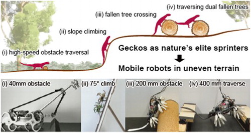
Figure 1. Target locomotive tasks. (A) A supposed scenario for locomotion in a forest. (B) The environment for robot experiments. In both (A) and (B), (i) high speed obstacle traversal, (ii) slope climbing, (iii) fallen tree crossing, (iv) dual fallen trees traversing.
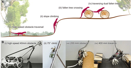
Figure 2. A meta-analysis of the results in [Citation22], in which asymmetric masses were attached to legged (A) and wheeled (B) robots crossing an obstacle: An experiment with static masses showed that biasing the mass distribution forward and backward had a significant effect on response to an obstacle during terrestrial locomotion. A whegs robot was strongly destabilised by tail mass (C) while rigid and soft wheeled robots were both helped by addition of a static head mass (D).
![Figure 2. A meta-analysis of the results in [Citation22], in which asymmetric masses were attached to legged (A) and wheeled (B) robots crossing an obstacle: An experiment with static masses showed that biasing the mass distribution forward and backward had a significant effect on response to an obstacle during terrestrial locomotion. A whegs robot was strongly destabilised by tail mass (C) while rigid and soft wheeled robots were both helped by addition of a static head mass (D).](/cms/asset/4359e604-947a-42db-80e0-f00c2eecbf36/tadr_a_1887760_f0002_oc.jpg)
Figure 3. After showing a noticeable effect with static mass changes [Citation22], we used a simulation to explore the effect of an elastic head (A). A neck and head were modelled as a mass (equal to 10% body mass) on a rigid rod, connected to the body via a torsional spring. (B) The simulation showed that the pitching of the body in response to an obstacle could be suppressed by the appropriate neck size and stiffness, although certain neck lengths and stiffnesses caused the robot to overturn (red shaded regions, indicating runs where the robot did not reach >2 m past the obstacle, or >10 body lengths). (C) RMS pitch rate over the entire run captures both pitch back and pitch forward afterward.
![Figure 3. After showing a noticeable effect with static mass changes [Citation22], we used a simulation to explore the effect of an elastic head (A). A neck and head were modelled as a mass (equal to 10% body mass) on a rigid rod, connected to the body via a torsional spring. (B) The simulation showed that the pitching of the body in response to an obstacle could be suppressed by the appropriate neck size and stiffness, although certain neck lengths and stiffnesses caused the robot to overturn (red shaded regions, indicating runs where the robot did not reach >2 m past the obstacle, or >10 body lengths). (C) RMS pitch rate over the entire run captures both pitch back and pitch forward afterward.](/cms/asset/19069477-a2c5-4ca1-8362-df55696e0e7f/tadr_a_1887760_f0003_oc.jpg)
Figure 4. (A) Side view of the elastic suspension robot prototype. (B) Top view of the slope climbing robot prototype, showing the drive components and the holder for a centre-biased added mass. (C) View of the active tail robot prototype, showing the novel wheg design and variable sprawl. The inset shows a CAD drawing of the compliant fin ray wheg.
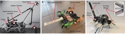
Table 1. Robot specs and features: Additional mass represents distributable mass on a neck or a tail. Body length excludes neck or tail length.
Table 2. Obstacle Traversal Success with varying tail stiffness.
Figure 5. Traversing an obstacle with an elastically suspended neck mass. We tested four different configurations: (A) An elastic neck with low stiffness, (B) an elastic neck actuated forward at the moment of obstacle contact, (c) an elastic neck with high stiffness and (C) no neck. The robot was then run over an obstacle, and the response recorded. We found that the actively moved neck showed the lowest pitch back (D), and that the presence of the neck in all configurations reduced the total perturbation (E). This allowed the robot to cross the obstacle more quickly (F).
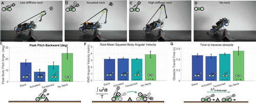
Figure 6. Climbing experiment results. (A) Example trajectories extracted from video data using DeepLabCut [Citation37]. (B) Soft tail sensor is able to sense pitch-back in the robot. In this case, the pitch-back leads to a catastrophic fall, but future robots could employ an active tail reflex to prevent loss of contact, the inset to the right shows an image the soft sensor. (C) Mean amplitude of pitch oscillations of the robot body at 45. The use of a tail significantly suppresses oscillation, and prevents loss of traction. (D) Tail increases speed due to the reduced oscillation, which means less foot slippage. Changing weight distribution also has an effect on the oscillations and reduced pitching results in a faster climb speed due to improved traction. (E) At 70
the robot is unable to climb without a tail. The addition of 20% additional mass at different locations has little impact on oscillations because the robot must climb at a lower speed, and so motion is steadier. (F) Again, speed and oscillation are consistent with each other.
![Figure 6. Climbing experiment results. (A) Example trajectories extracted from video data using DeepLabCut [Citation37]. (B) Soft tail sensor is able to sense pitch-back in the robot. In this case, the pitch-back leads to a catastrophic fall, but future robots could employ an active tail reflex to prevent loss of contact, the inset to the right shows an image the soft sensor. (C) Mean amplitude of pitch oscillations of the robot body at 45∘. The use of a tail significantly suppresses oscillation, and prevents loss of traction. (D) Tail increases speed due to the reduced oscillation, which means less foot slippage. Changing weight distribution also has an effect on the oscillations and reduced pitching results in a faster climb speed due to improved traction. (E) At 70∘ the robot is unable to climb without a tail. The addition of 20% additional mass at different locations has little impact on oscillations because the robot must climb at a lower speed, and so motion is steadier. (F) Again, speed and oscillation are consistent with each other.](/cms/asset/32bc714f-f3af-4153-ac71-a3187602436b/tadr_a_1887760_f0006_oc.jpg)
Figure 7. (A) Side view of a climbing gecko, showing the use of the tail to recover from a forefoot slip [Citation21]. (B)–(D) Image sequences showing the robot traversing a 30 mm obstacle. (B) 45 ramp angle, 4 successful trials. (C) 50
ramp angle, 2 successful trials out of 4. (D) 60
ramp angle, 2 successful trials out of 4. (E) 75
ramp angle which the robot successfully climbed.
![Figure 7. (A) Side view of a climbing gecko, showing the use of the tail to recover from a forefoot slip [Citation21]. (B)–(D) Image sequences showing the robot traversing a 30 mm obstacle. (B) 45∘ ramp angle, 4 successful trials. (C) 50∘ ramp angle, 2 successful trials out of 4. (D) 60∘ ramp angle, 2 successful trials out of 4. (E) 75∘ ramp angle which the robot successfully climbed.](/cms/asset/fed5094b-3b5c-4aa4-9431-b9495ee558b9/tadr_a_1887760_f0007_oc.jpg)
Figure 8. The climbing robot traversing a large obstacle (obstacle height = body length). (A) Image sequence of a successful traversal with a tail of medium stiffness, showing the robot (from left to right) approaching the obstacle, pitching backward as it ascends, actuating its tail to prevent loss of contact, and having ascended the obstacle. (B) Time history of several obstacle ascent trials, showing failed ascents with the tail remaining unused at 130 and successful ascents using the active tail. (C) Tail angle time histories of the same set of traversal tests. Change of tail angle during pitch-back is due to the robot's weight bending the tail back. (D) Robot failing to scale obstacle with a soft tail, climbing obstacle with a compliant tail and using a rigid tail to actively aid the ascent.
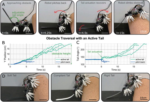
Figure 9. Dual obstacle traversal fails with a rigid tail (A) but is successful with a soft tail (B).
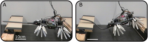
Table 3. Dual Obstacle Traversal Success.
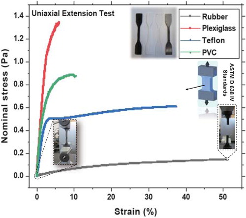
Figure A1. Tensile tests of the materials used for the tails of varying compliance, performed with an Instron using ASTM D 638 IV standard samples.