797
Views
50
CrossRef citations to date
0
Altmetric
Original

A head and neck hyperthermia applicator: Theoretical antenna array design

, , &
Pages 59-67 | Received 01 Dec 2006, Accepted 04 Dec 2006, Published online: 09 Jul 2009

Figures & data

Figure 1. 3D view (a, c) and sagittal cuts (b, d) of the tissue distribution of the two head models. (b) and (d) show the RT position and an indication of the HT position (10° rotation).
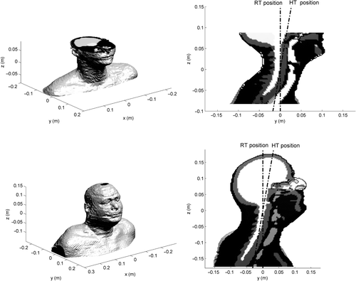
Figure 1. 3D view (a, c) and sagittal cuts (b, d) of the tissue distribution of the two head models. (b) and (d) show the RT position and an indication of the HT position (10° rotation).

Table I.  Dielectric properties at 433 MHz of the tissues types corresponding to the two head models (μr = 1.0).

Figure 2. Multiple antenna ring arrangements and a schematic sagittal view in HT position.

Figure 2. Multiple antenna ring arrangements and a schematic sagittal view in HT position.

Figure 3. Cross-sections of the PA distributions in the large patient model in HT position for one ring of eight dipoles (1 × 8, R = 20 cm) and two rings of six dipoles (2 × 6, R = 20 cm, D = 6 cm). Black arrows indicate the locations of PA hotspots (1 × 8) or corresponding locations where these hotspots are reduced (2 × 6).
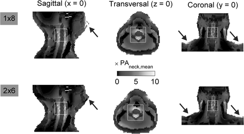
Figure 3. Cross-sections of the PA distributions in the large patient model in HT position for one ring of eight dipoles (1 × 8, R = 20 cm) and two rings of six dipoles (2 × 6, R = 20 cm, D = 6 cm). Black arrows indicate the locations of PA hotspots (1 × 8) or corresponding locations where these hotspots are reduced (2 × 6).

Figure 4. Average PA ratios as a function of antenna ring radius for a setup of eight antennas: setup (a) and results (b). Curves correspond to results for a small and a large patient model in RT and HT (10°rotation around the x-axis) position. The average radius of these models and the near field distance (λ/2), where the dipole antennas should not be placed, are indicated.
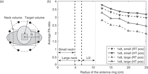
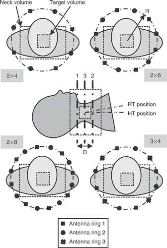
Figure 4. Average PA ratios as a function of antenna ring radius for a setup of eight antennas: setup (a) and results (b). Curves correspond to results for a small and a large patient model in RT and HT (10°rotation around the x-axis) position. The average radius of these models and the near field distance (λ/2), where the dipole antennas should not be placed, are indicated.
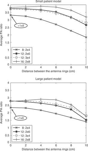
Figure 5. aPA ratios for different distances between the outer rings. Curves are shown corresponding to the 2 × 4, 2 × 6, 2 × 8 and 3 × 4 arrangements.

Figure 5. aPA ratios for different distances between the outer rings. Curves are shown corresponding to the 2 × 4, 2 × 6, 2 × 8 and 3 × 4 arrangements.

Reprints and Corporate Permissions

Please note: Selecting permissions does not provide access to the full text of the article, please see our help page How do I view content?

To request a reprint or corporate permissions for this article, please click on the relevant link below:

Academic Permissions

Please note: Selecting permissions does not provide access to the full text of the article, please see our help page How do I view content?

Obtain permissions instantly via Rightslink by clicking on the button below:

If you are unable to obtain permissions via Rightslink, please complete and submit this Permissions form. For more information, please visit our Permissions help page.