
Figures & data
Figure 1. Histotripsy techniques and associated representative acoustic parameters. The year refers to the time when each technique was first reported in literature, but not yet necessarily termed the way it is currently known. HIFU transducer F‐number is the ratio of its radius of curvature (focal length) to the aperture diameter. The first two types are typically used at frequencies less than 1 MHz, and last two at frequencies higher than 1 MHz.
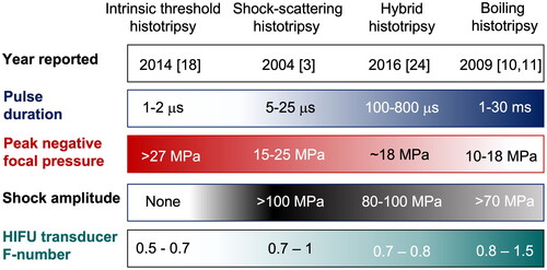
Figure 2. Comparison of typical focal pressure waveforms (top row), free-field axial beam profiles (middle row), and resulting bubble distributions for intrinsic threshold histotripsy (left column), shock-scattering histotripsy (middle column), and boiling histotripsy (right column). for intrinsic threshold histotripsy, a short pulse is generated with a single dominant tensile pressure cycle exceeding the intrinsic threshold. Both shock-scattering histotripsy and boiling histotripsy utilize focal pressure waveforms containing high amplitude shocks at the focus, and a bubble cloud forms due to interaction of the shocks with an initially formed (incidental) bubble. In shock-scattering histotripsy, the initial bubble forms in response to one or more tensile phases of the excitation pressure, while shock-induced heating causes the primary vapor bubble to form in boiling histotripsy. Note that the bubbles have not been drawn to scale.
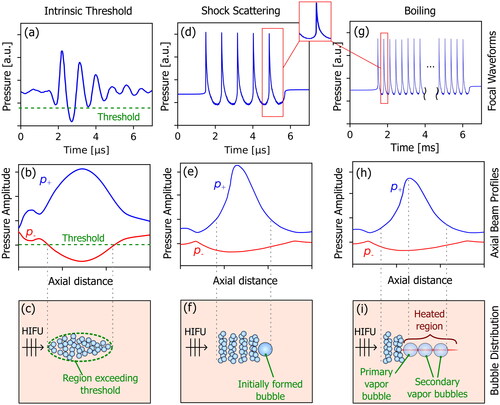
Figure 3. Examples of transducers used for intrinsic threshold histotripsy (a, b), shock-scattering histotripsy (c, d), and boiling histotripsy (e, f, g). subfigures (a) and (b) are modified from [Citation75] and [Citation73], respectively, and are licensed under a creative commons attribution license (CC by 4.0).
![Figure 3. Examples of transducers used for intrinsic threshold histotripsy (a, b), shock-scattering histotripsy (c, d), and boiling histotripsy (e, f, g). subfigures (a) and (b) are modified from [Citation75] and [Citation73], respectively, and are licensed under a creative commons attribution license (CC by 4.0).](/cms/asset/cd6c1050-f8d4-49f9-8b22-38ac53759e8c/ihyt_a_2233720_f0003_c.jpg)