Figures & data
1 Integrated gasification combined cycle system including pre-combustion CO2 removalCitation3
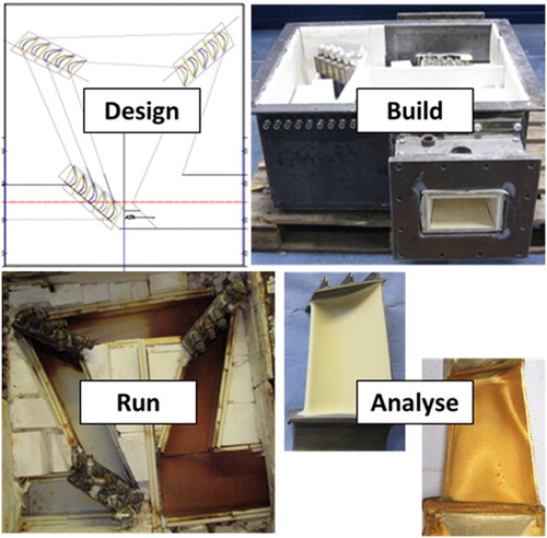
2 Schematic diagrams of the burner rig designed to simulate IGT combustion conditions using a cylindrical air-cooled samples and b after modification to include a cascade of air-cooled blades

3 Blade geometries determined the angles blades were mounted at in the cascade; three blades per cascade stage were in the centre of the combusted gas stream and the remaining two blades were integrated into the gas stream containment wall
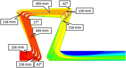
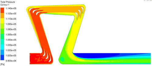
4 Results of CFD calculations of combustion gas stream pressure drops throughout the cascade
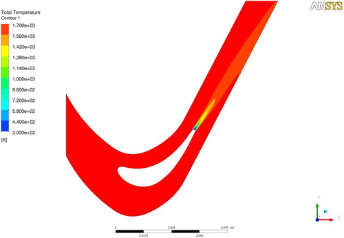
5 Results of CFD calculations show that the cooling air leaving the trailing edge of a cascade blade mixes well with the general hot gas flow before it interacts with the next cascade stage
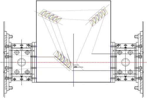
6 General assembly drawing of the overall cascade system showing the positions of the three cascade stages, position of the hot gas path for the combusted gases, as well as the cascade hot gas inlet (left side) and exit (right side)
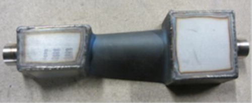
7 The boxes fitted the blade root and shroud to the blades’ modified cooling air supply and partial exit, respectively. The blade root (cooling air inlet) is to the right. The blade shroud (main cooling air exit) is to the left
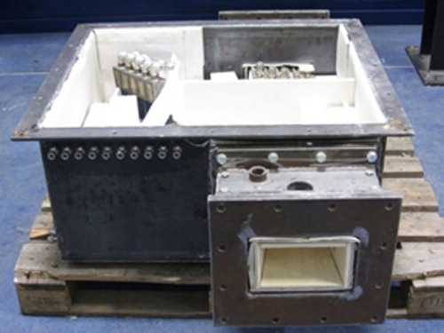
8 Photograph of cascade midway through its construction. The cascade inlet is at the front right, and outlet at the back. In the top left, the third and final stage of cascade blades can be seen
9 Four different TBC coating systems (ceramic and bond coat combinations, indicated by different colours) were applied to blades in the centre of each cascade stage. The blades that formed the cascade walls in each cascade stage (shown in black-and-white) were coated with just the metallic corrosion-resistant coating Sicoat 2464

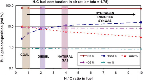
10 Calculated concentrations of species expected for different fuels (defined by their hydrogen to carbon ratio) assuming combustion where lambda is 1.75
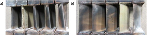
11 Photographs taken of the a leading and b trailing edges of blades exposed in the second stage of the cascade after its removal following the 300 h cascade/modified burner rig commissioning run. Note the presence of one ‘white’ blade that had over-heated due to a faulty cooling air supply system
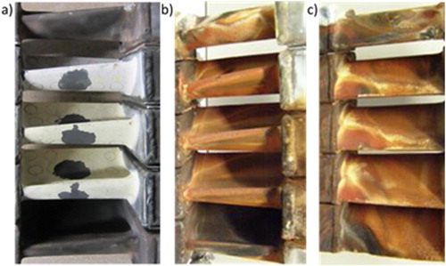
12 Cassette of blades from the first cascade stage of the initial 1000 h trial showing: a leading edge pre-exposure, b leading edge post-exposure and c trailing edge post-exposure
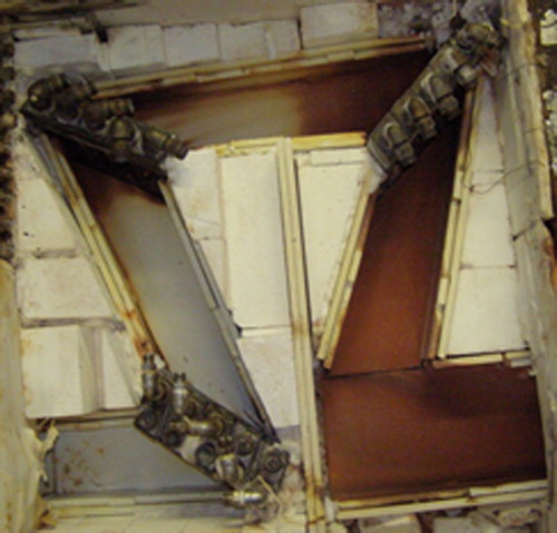
13 Photograph of the cascade gas path after the 1000 h trial showing the development of red/brown discolouration between the second and third cascade stages
14 (left) Erosion of TBC coating can be visually observed on the leading edge of some blades post-exposure. (right) SEM/EDX data shows hot corrosion following the loss of part of a TBC. Cross-section taken at 50% of blade height
15 Some blades showed extensive cracking and delamination of the TBC post-exposure. Cross-section taken at 50% of blade height
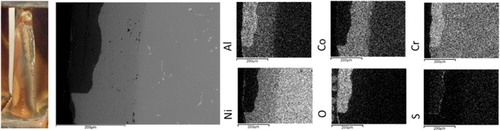
16 SEM/EDX mapping images show the presence of oxidation and hot corrosion post-exposure. Cross-section taken at 50% of blade height