Figures & data
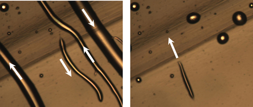
Figure 1. (Colour online) Surface transport of LC material (DIO) on X-cut LN:Fe crystal induced by heating from 23°C to 110°C by the rate of 5°C/min. The corresponding pyroelectric field ‘pulls’ the LC from the top to the side walls (Z-planes) of the crystal. (Dark strip-shaped region on the substrate corresponds to the area that was pre-illuminated with the green laser beam).
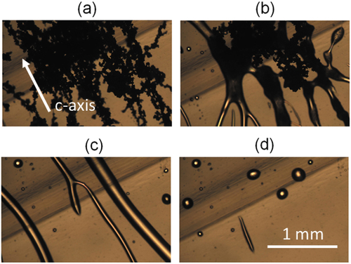
Figure 2. (Colour online) Droplets of LC material (DIO) on the LN:Fe crystal during cooling from 110°C to 80°C: (a) before cooling, (b) during cooling the droplets start to elongate, (c) then they abruptly transform into running streams, (d) the streams become thinner when the temperature starts to stabilise. In the top left corner (highlighted in green in the region pre-illuminated by the 532-nm laser light can be seen. Image (c) is very bright in comparison to the others because a layer of LC material traveled into the gap between the bottom surface of the LN:Fe crystal and the underlying glass slide.
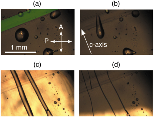
Figure 3. (Colour online) (a) Spiked conical formations observed at the edge of the LC layer trapped in-between the LN:Fe crystal and the glass plate during cooling into the NF phase. (b, c) the isolated spiky droplets move around in the image area.
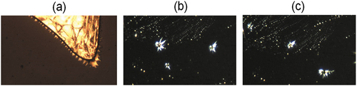
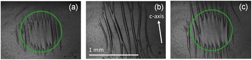
Figure 4. (Colour online) Droplets of LC material (DIO) on the X-cut LN:Fe crystal at 110°C: (a) before illumination, (b, c) tendril-like structures formed during illumination. The green circles in (b) and (c) indicate the illuminated area. (d) Inverse response time of the process as a function of laser power.
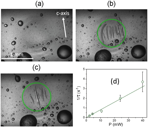
Figure 5. (Colour online) Illumination-induced tendrils of the LC material (DIO) formed on the surface of the X-cut LN:Fe crystal at 55°C: (a, c) during illumination, (b) when the illumination was shortly switched off. The green circles in (a) and (c) indicate the illuminated area.