871
Views
5
CrossRef citations to date
0
Altmetric
Original Articles

A New Aircraft Inlet for Sampling Interstitial Aerosol: Design Methodology, Modeling, and Wind Tunnel Tests

, , &
Pages 885-894 | Received 14 Oct 2012, Accepted 29 Mar 2013, Published online: 24 May 2013

Figures & data

FIG. 1 Design concept of the BASE. The interstitial inlet is located toward the aft of the blunt body housing, below the line of sight of large droplets, and above the region where shatter particles are present. (Color figure available online.)
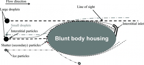
FIG. 1 Design concept of the BASE. The interstitial inlet is located toward the aft of the blunt body housing, below the line of sight of large droplets, and above the region where shatter particles are present. (Color figure available online.)

FIG. 2 Particle trajectories around double cone geometries of different aspect ratios. (a) and (b): Particle size separation increases with decreasing front cone chord length. (c) At very short cone chord lengths, flow separation results and size separation region decreases. All dimensions are in inches.
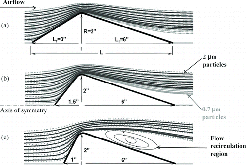
FIG. 2 Particle trajectories around double cone geometries of different aspect ratios. (a) and (b): Particle size separation increases with decreasing front cone chord length. (c) At very short cone chord lengths, flow separation results and size separation region decreases. All dimensions are in inches.

FIG. 3 The final shape of the BASE blunt body housing. Particle trajectories for 2 μm and 0.7 μm are shown on the top half of the geometry and flow streamlines are shown in the lower half. The location of the interstitial inlet is indicated with a line segment.
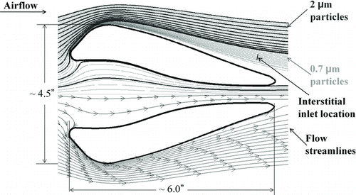
FIG. 3 The final shape of the BASE blunt body housing. Particle trajectories for 2 μm and 0.7 μm are shown on the top half of the geometry and flow streamlines are shown in the lower half. The location of the interstitial inlet is indicated with a line segment.

FIG. 4 Particle trajectories for the 3D geometry.

FIG. 4 Particle trajectories for the 3D geometry.

FIG. 5 Sampling efficiency of the inlet as function of aerodynamic diameter and Stokes number. The Stokes number is calculated based on freestream velocity and blunt body diameter.
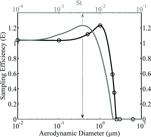
FIG. 5 Sampling efficiency of the inlet as function of aerodynamic diameter and Stokes number. The Stokes number is calculated based on freestream velocity and blunt body diameter.

FIG. 6 The calculated sampling efficiencies of simulated shatter particles injected at the surface of the blunt body housing with 100 ms−1 normal velocity with respect to the surface of the body.
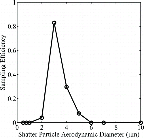
FIG. 6 The calculated sampling efficiencies of simulated shatter particles injected at the surface of the blunt body housing with 100 ms−1 normal velocity with respect to the surface of the body.

FIG. 7 The schematic diagram of the wind tunnel experimental setup used for initial validation of the BASE design concept.
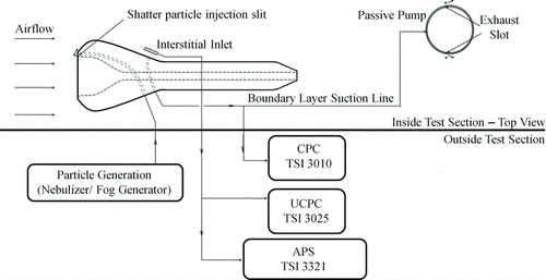
FIG. 7 The schematic diagram of the wind tunnel experimental setup used for initial validation of the BASE design concept.

FIG. 8 Wind tunnel measurements of total number concentrations in the BASE boundary layer and interstitial inlet sample flow for cases of: no shatter particle injection (0–60 s) and nebulized shatter particle injection (60–120 s).
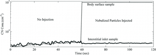
FIG. 8 Wind tunnel measurements of total number concentrations in the BASE boundary layer and interstitial inlet sample flow for cases of: no shatter particle injection (0–60 s) and nebulized shatter particle injection (60–120 s).

FIG. 9 Wind tunnel measurements of particle size distribution in the BASE boundary layer and interstitial inlet sample flow for cases of: no shatter particle injection and nebulized shatter particle injection.
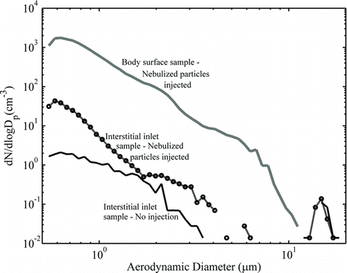
FIG. 9 Wind tunnel measurements of particle size distribution in the BASE boundary layer and interstitial inlet sample flow for cases of: no shatter particle injection and nebulized shatter particle injection.

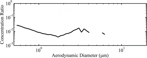
FIG. 10 Ratio of shatter particle concentration in the interstitial inlet to that in the body surface sample

as a function of particle size for the nebulized particle injection case.

FIG. 10 Ratio of shatter particle concentration in the interstitial inlet to that in the body surface sample Display full size as a function of particle size for the nebulized particle injection case.

FIG. 11 Shatter particle size distribution in the interstitial inlet and the body surface sample and their ratio for the fog particle injection case.
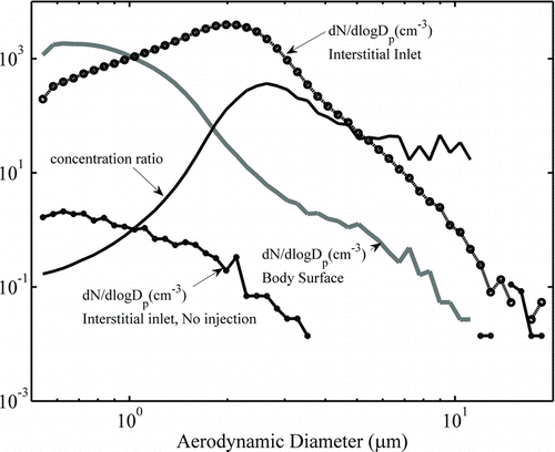
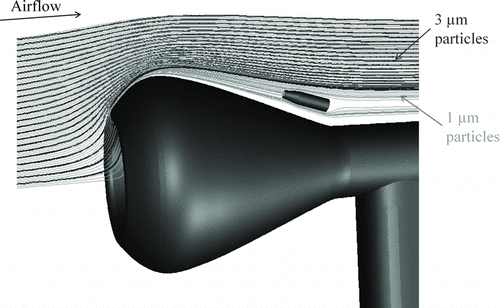
FIG. 11 Shatter particle size distribution in the interstitial inlet and the body surface sample and their ratio for the fog particle injection case.
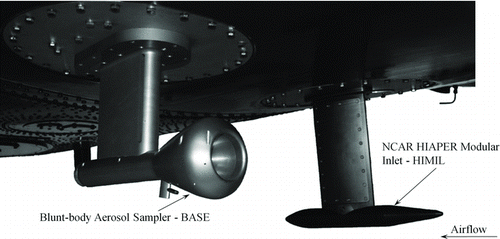
FIG. 12 BASE and HIMIL aerosol inlets installed on the belly of the NSF/NCAR C-130 aircraft during the PLOWS campaign.

FIG. 12 BASE and HIMIL aerosol inlets installed on the belly of the NSF/NCAR C-130 aircraft during the PLOWS campaign.

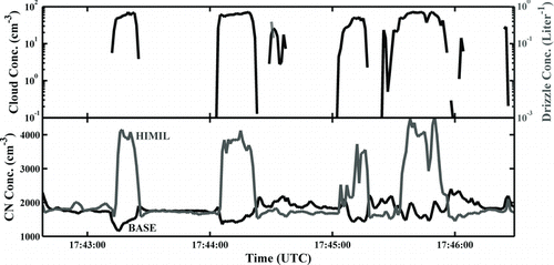
FIG. 13 Performance of the HIMIL and BASE inlets on NSF/NCAR C-130 aircraft in a drizzle-free cloud penetration case.

FIG. 13 Performance of the HIMIL and BASE inlets on NSF/NCAR C-130 aircraft in a drizzle-free cloud penetration case.

Reprints and Corporate Permissions

Please note: Selecting permissions does not provide access to the full text of the article, please see our help page How do I view content?

To request a reprint or corporate permissions for this article, please click on the relevant link below:

Academic Permissions

Please note: Selecting permissions does not provide access to the full text of the article, please see our help page How do I view content?

Obtain permissions instantly via Rightslink by clicking on the button below:

If you are unable to obtain permissions via Rightslink, please complete and submit this Permissions form. For more information, please visit our Permissions help page.