Figures & data
FIG. 1. Schematic of the smoke generation, collection, and measurement system. The piston is within a six-liter cylinder.
FIG. 2. Photograph of heating wire with silicone rubber (upper) and Kapton samples after heating. The samples are about 11 mm long with a 5 mm diameter.
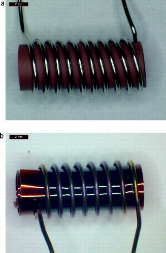
TABLE 1 Uncertainty for measured smoke properties mL, Mc, Y, ρ, and dm
FIG. 3. Mass loss vs. wire temperature: low-gravity, flow—open symbols; low-gravity, no flow—black symbols; normal gravity, flow—gray symbols. Pyrell—diamond, lamp wick—square, silicone rubber—triangle, Kapton— inverted triangle, Teflon—circle.
FIG. 4. TEM images of smoke particles generated by Teflon, Pyrell, lamp wick, and Kapton. The reference length scale is 2 μm in length.
FIG. 5. TEM images of the residue of the smoke particles generated by silicone rubber. The reference length scale at bottom of the image is 2 μm in length.
FIG. 6. Smoke yield versus wire temperature: low-gravity, flow—open symbols; normal gravity, flow (8 cm/s)—solid symbols. Same symbol identification as .

FIG. 7. The smoke plume from silicone rubber, lamp wick, and Teflon for no flow. The horizontal field of view is about 6 cm. The white bullet shape and white “bat-wings” (Teflon) are light scattered by the smoke. The illumination near the wire for Teflon is likely from the reflection of high-temperature IR radiation from the wall of the aluminum tube. The white dot near the center is a thermistor located in the center of the tube. Flow is from left to right.
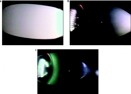
FIG. 8. Smoke plumes from silicone rubber, lamp wick, and Teflon at a flow of 8 cm/s. The samples each have a length of about 11 mm and a diameter of about 5 mm.
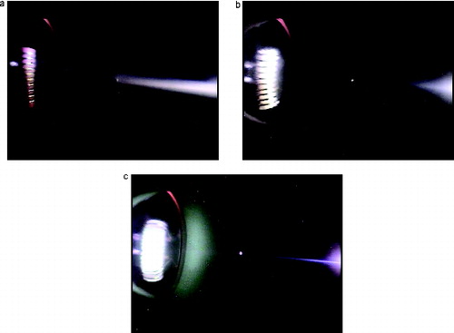
FIG. 9. Photographs of the Pyrell smoke plume expanding to the right at 7 s, 16 s, and 33 s after heater is turned on.
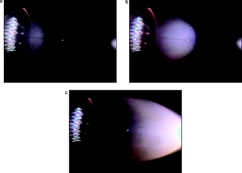
FIG. 10. Approach to steady state temperature for six no-flow measurements and one with a flow of 8 cm/s. The quantity Tred is the normalized temperature difference, (T – Ti)/(Tss – Ti).
FIG. 11. The diameter of average mass versus temperature: low-gravity, flow—open symbols; low-gravity, no flow—solid symbols. Same symbol identification as .
FIG. 12. TEM images of Pyrell smoke for flow (left image) and no-flow (right image). Black scale bar in the bottom of each images is 5 μm in length.