1,092
Views
11
CrossRef citations to date
0
Altmetric
ARTICLES

Effect of potassium on a model soot combustion: Raman and HRTEM evidences

, , , , &
Pages 405-415 | Received 14 Oct 2015, Accepted 03 Feb 2016, Published online: 01 Mar 2016

Figures & data

Table 1. BET analysis (SA, m2/g) at different soot conversion values.

Figure 1. Fringes extraction from Printex U HRTEM micrograph: (A) image selection; (B) filtered image; (C) threshold analysis; (D) skeletonized image (in the inset is shown the BSU parameters evaluated in the fringe analysis).
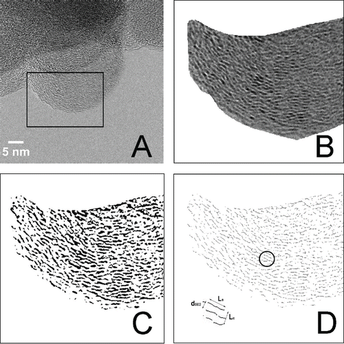
Figure 1. Fringes extraction from Printex U HRTEM micrograph: (A) image selection; (B) filtered image; (C) threshold analysis; (D) skeletonized image (in the inset is shown the BSU parameters evaluated in the fringe analysis).

Table 2. Primary size distributions obtained by TEM measurements, XRD, and TEM crystallographic parameters (the mean interlayer spacing between carbon layers d002 (nm), average height Lc (nm), and average width La (nm) of BSU) of soot and K-soot samples at different oxidation degrees.

Figure 2. XRD measurement of unoxidized soot and K-soot samples.

Figure 2. XRD measurement of unoxidized soot and K-soot samples.

Figure 3. TEM images of fresh samples. (A) Low magnification bright field TEM micrograph of fresh Printex U; (B) High resolution TEM of fresh Printex U; (C) Low magnification bright field TEM micrograph of fresh K-doped Printex U; (D) High resolution TEM of fresh K-doped Printex U. The insets in A and C report the primary particle size distributions of fresh Printex U and K-doped Printex U, respectively.
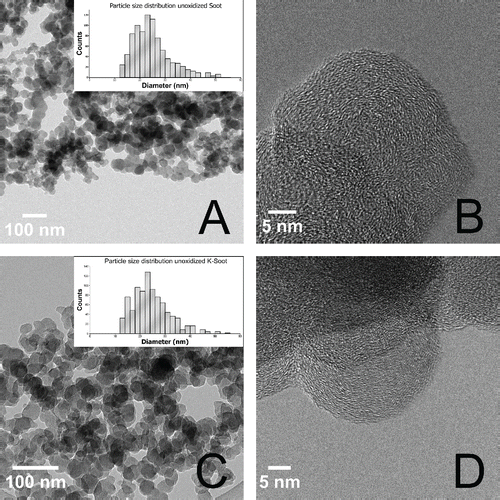
Figure 3. TEM images of fresh samples. (A) Low magnification bright field TEM micrograph of fresh Printex U; (B) High resolution TEM of fresh Printex U; (C) Low magnification bright field TEM micrograph of fresh K-doped Printex U; (D) High resolution TEM of fresh K-doped Printex U. The insets in A and C report the primary particle size distributions of fresh Printex U and K-doped Printex U, respectively.

Figure 4. Raman spectra (632 nm excitation, 100 µW laser power) recorded over fresh Printex U and K-doped Printex U samples.
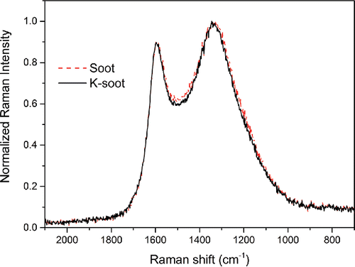
Figure 4. Raman spectra (632 nm excitation, 100 µW laser power) recorded over fresh Printex U and K-doped Printex U samples.

Figure 5. Raman spectra (632 nm excitation, 100 µW laser power) recorded over oxidized Printex U (A) and K-doped Printex U (B) samples under O2 and O2/NO2 (oxidation state near 40% in both cases).
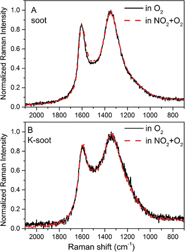
Figure 5. Raman spectra (632 nm excitation, 100 µW laser power) recorded over oxidized Printex U (A) and K-doped Printex U (B) samples under O2 and O2/NO2 (oxidation state near 40% in both cases).

Figure 6. First-order Raman spectra of Printex U at different oxidation degrees (curve a = 0%, b = 20%, c = 40%, d = 50%, e = 60 %) under O2/NO2 at 200°C.
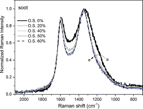
Figure 6. First-order Raman spectra of Printex U at different oxidation degrees (curve a = 0%, b = 20%, c = 40%, d = 50%, e = 60 %) under O2/NO2 at 200°C.

Figure 7. TEM images of partially oxidized samples (60% in the case of Printex U, 64% in the case of K-doped Printex U). (A) Low magnification bright field TEM micrograph of oxidized Printex U; (B) High resolution TEM of oxidized Printex U; (C) Low magnification bright field TEM micrograph of oxidized K-doped Printex U; (D) High resolution TEM of oxidized K-doped Printex U. Insets in B and D report the fringes extracted images of the areas indicated by the boxes. The area in the inset B (oxidized Printex U 60%) clearly exhibits a higher graphitization degree (higher La and Lc) in comparison to the inset D (oxidized K-doped Printex U 64%). The insets in A and C report the primary particle size distributions of oxidized Printex U 60% and K-doped Printex U 64%, respectively.
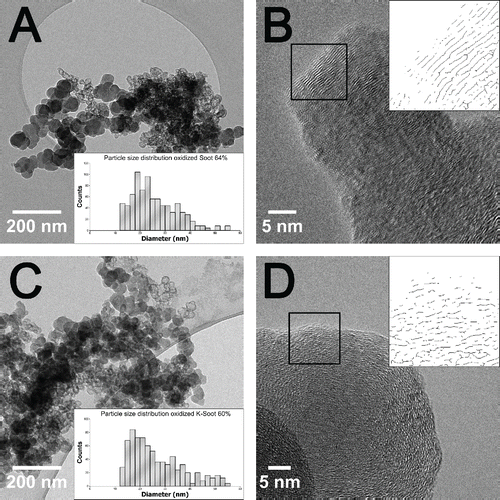
Figure 7. TEM images of partially oxidized samples (60% in the case of Printex U, 64% in the case of K-doped Printex U). (A) Low magnification bright field TEM micrograph of oxidized Printex U; (B) High resolution TEM of oxidized Printex U; (C) Low magnification bright field TEM micrograph of oxidized K-doped Printex U; (D) High resolution TEM of oxidized K-doped Printex U. Insets in B and D report the fringes extracted images of the areas indicated by the boxes. The area in the inset B (oxidized Printex U 60%) clearly exhibits a higher graphitization degree (higher La and Lc) in comparison to the inset D (oxidized K-doped Printex U 64%). The insets in A and C report the primary particle size distributions of oxidized Printex U 60% and K-doped Printex U 64%, respectively.
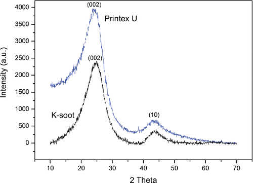
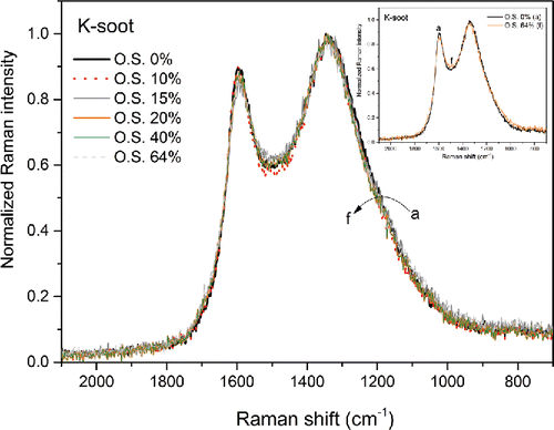
Figure 8. First-order Raman spectra of K-doped Printex U at different oxidation degrees (curve a = 0%, b = 10%, c = 15%, d = 20 %, e = 40 %, f = 64 %) under O2/NO2 at 200°C.

Figure 8. First-order Raman spectra of K-doped Printex U at different oxidation degrees (curve a = 0%, b = 10%, c = 15%, d = 20 %, e = 40 %, f = 64 %) under O2/NO2 at 200°C.

Reprints and Corporate Permissions

Please note: Selecting permissions does not provide access to the full text of the article, please see our help page How do I view content?

To request a reprint or corporate permissions for this article, please click on the relevant link below:

Academic Permissions

Please note: Selecting permissions does not provide access to the full text of the article, please see our help page How do I view content?

Obtain permissions instantly via Rightslink by clicking on the button below:

If you are unable to obtain permissions via Rightslink, please complete and submit this Permissions form. For more information, please visit our Permissions help page.