Figures & data
Table 1. Characteristics of the range hoods evaluated in the study.
Figure 1. Contour plots of mean background-removed particle concentrations and size distributions measured under Fan Off After Cooking test condition, from 15 min before cooking to 3 h after cooking, by range hood flow rate. The time of 0 represents the end of cooking.
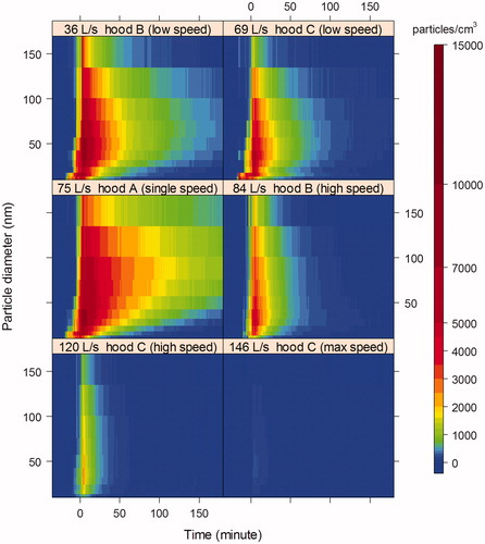
Figure 2. Average particle peak concentration as a function of particle size at each range hood flow rate, measured under Fan Off After Cooking test condition. The error bars represent standard errors of the mean based on replication tests. Only the plus side of the error bars is shown to minimize overlapping. The x-axis is logarithmic.
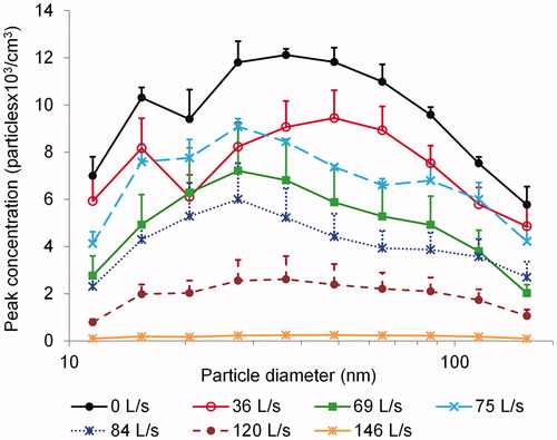
Table 2. The size-resolved UFP peak reduction with six range hood flow rates.
Figure 3. The top panel presents the cumulative exposure to total particles due to cooking over the entire monitoring period, measured under Fan Off After Cooking test condition. The x-axis represents the time relative to the end of cooking (t = 0). The bottom panel shows the time-integrated exposure over the cooking period and each hour after cooking ended, measured under Fan Off After Cooking test condition.
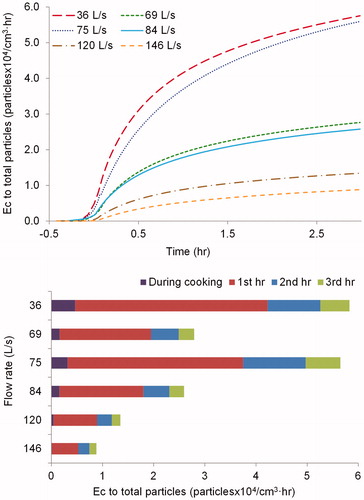
Figure 4. A comparison of mean deposition rate of the total particles and the mean air exchange rate at each range hood flow rate, measured under Fan Always On test condition. The flow rate of 75 L/s was excluded due to large uncertainties.
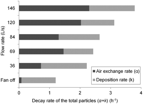
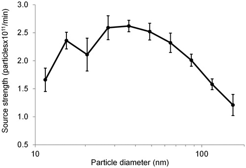
Figure 5. The source strength distribution for particles in the size range of 10–178 nm due to cooking on a gas stove. The error bars represent the propagation of standard errors that took into account uncertainties from estimated particle decay rate and peak concentration.