Figures & data
Table 1. Wish-list for automated rectal cancer treatment planning for an MRL.
Table 2. Comparison of dosimetric plan parameters for MANplans and AUTOplans.
Figure 1. Absolute differences in dosimetric plan parameters between the MANplans and AUTOplans for all 23 patients. Positive values indicate a better AUTOplan. The first 5 patients were used to train the automated treatment planning workflow.
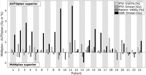
Figure 2. Dose distributions for the MANplan (left) and AUTOplan (right) for patient 14 (See ). The AUTOplan had clearly reduced dose in the OAR. Top: axial view, bottom sagittal view. Magenta contour = PTV, Red contour = OAR.
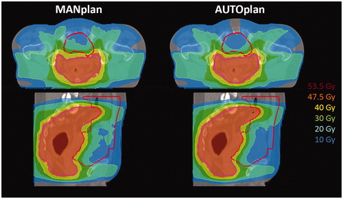
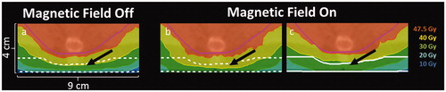
Figure 3. Parts of axial dose distribution for patient 14 (in PTV and posterior to PTV) (a) clinically acceptable dose distribution without magnetic field (6 MV conventional linac plan). (b) clinically unacceptable dose distribution with magnetic field (MRL plan) but no dose control by back structure; too high dose in back structure (arrow) related to ERE and enhanced build-up due to the magnetic field. (c) clinically acceptable dose distribution with magnetic field (MRL plan) and dose control using the back structure. Pink contour = PTV, dashed white contour = inactive back structure, solid white contour = active back structure. The treatment couch matrass is located right below the back structure.