Figures & data
Figure 1. Scheme of rotary dryer in (a) overall composition (b) cylinder structure. 1. Mass flow controller for compressed air, 2. Air heater, 3. Temperature controller for air heater, 4. Temperature controller for drying air, 5. Rotary joint, 6. Cylinder, 7. Cylinder motor, 8. Air distribute plate, 9. Jacket, 10. Lifter, 11. Oil bath, 12. Heating rod, 13. Outlet, 14. Temperature controller for cylinder.
Table 1. Two-stage drying conditions.
Figure 2. Drying-rate curves of two-stage drying by different temperature combinations.
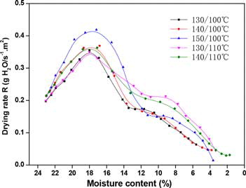
Figure 3. Drying-rate curves of two-stage drying by different intermediate moisture contents.
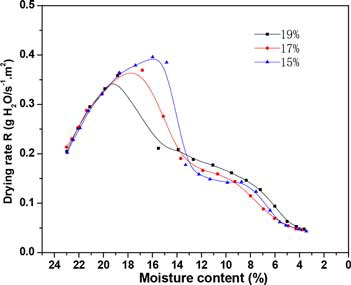
Figure 4. Drying-rate curves of single-stage drying.
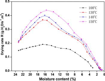
Table 2. Drying time and average drying rate for different drying methods.
Figure 5. Maillard reaction compounds contents in single-stage- and two-stage-dried cut tobacco.
Figure 6. Carotenoid degradation products contents in single-stage- and two-stage-dried cut tobacco.
Table 3. Maillard reaction compounds contents in dried cut tobacco for different drying processes (µg/g).
Table 4. Carotenoid degradation products contents in dried cut tobacco for different drying processes (µg/g).
Figure 7. Comparison of pre-drying and final temperatures’ effect on Maillard reaction compounds retentions.
Figure 8. Comparison of pre-drying and final temperatures’ effect on carotenoid degradation product retentions.

Figure 9. Effect of intermediate moisture content on Maillard reaction compounds retentions.
Figure 10. Effect of intermediate moisture content on carotenoid degradation product retentions.