3,568
Views
7
CrossRef citations to date
0
Altmetric
Review Articles

Membrane bioreactors for syngas permeation and fermentation

, , , &
Pages 856-872 | Received 27 Jan 2021, Accepted 04 Jul 2021, Published online: 15 Sep 2021

Figures & data

Figure 1. Schematic representation of the simplified Wood–Ljungdahl pathway of acetogens and their (native) metabolic end products [Citation1,Citation2]. Acetogenic microorganisms are able to produce different combinations of the depicted organic products, depending on their metabolism.

Figure 1. Schematic representation of the simplified Wood–Ljungdahl pathway of acetogens and their (native) metabolic end products [Citation1,Citation2]. Acetogenic microorganisms are able to produce different combinations of the depicted organic products, depending on their metabolism.

Table 1. Expression of local mass transfer coefficients.

Table 2. Expression of overall mass transfer coefficients (based on the liquid side), for gas–liquid membrane contacting applications [Citation25].

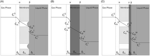
Figure 2. Concentration profile of compound i when moving from the gas to liquid phase through a: hydrophobic microporous membrane (A), dense membrane (B) and integral asymmetric/composite membrane (C). CiG: concentration of i in the gas phase, Ci L: concentration of i in the liquid phase, CiM: concentration of i in the membrane phase, δg: thickness of gas boundary layer; δl: thickness of liquid boundary layer; δm: thickness of membrane boundary layer, α: gas-membrane interface, β: membrane-liquid interface, γ: microporous-dense layers interface.

Figure 2. Concentration profile of compound i when moving from the gas to liquid phase through a: hydrophobic microporous membrane (A), dense membrane (B) and integral asymmetric/composite membrane (C). CiG: concentration of i in the gas phase, Ci L: concentration of i in the liquid phase, CiM: concentration of i in the membrane phase, δg: thickness of gas boundary layer; δl: thickness of liquid boundary layer; δm: thickness of membrane boundary layer, α: gas-membrane interface, β: membrane-liquid interface, γ: microporous-dense layers interface.

Table 3. Design parameters for membrane module selection. [Citation26].

Table 4. Different HFM reactor configurations studied for syngas mass transfer, respective characteristics and the maximum KLa reported.

Table 5. HFM bioreactor configurations for syngas fermentation and respective operational conditions.

Table 6. Summary of flow configurations in a hollow fiber membrane reactor and their respective advantages.

Figure 3. HFM modules with (A) tubesheets at both ends; (B) a single tubesheet in a U shaped bundle; (C) one tubesheet and one sealed end; (D, E) gas feed entering the bundle from the perforations on the central tube and exiting from (D) the port on the housing or (E) the perforations toward the other end; (F) Baffles with alternating clearances at top and bottom to force the flow up and down. Based on [Citation41].

Figure 3. HFM modules with (A) tubesheets at both ends; (B) a single tubesheet in a U shaped bundle; (C) one tubesheet and one sealed end; (D, E) gas feed entering the bundle from the perforations on the central tube and exiting from (D) the port on the housing or (E) the perforations toward the other end; (F) Baffles with alternating clearances at top and bottom to force the flow up and down. Based on [Citation41].