Figures & data
Table 1. Parameter constants for the potential functions.[Citation30]
Figure 1. (Colour online) (a) A schematic illustration of a graphene sheet showing the edge atoms constrained (shaded in grey) for the application of the pre-defined strain rate. (b) and (c) illustrate the loading direction of an armchair (AC) sheet and zigzag (ZZ) sheet, respectively.
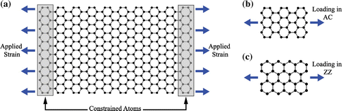
Figure 2. (Colour online) Results for elastic modulus, fracture stress and fracture strain for AC- and ZZ-oriented graphene with increasing sheet size for two different temperatures: (a) 0 K and (b) 300 K. In all graphs, our MD results are represented by solid circles for the AC direction and inverted triangles for the ZZ direction, while dashed lines represent bulk mechanical properties.
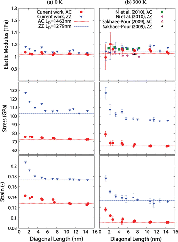
Figure 3. (Colour online) (a) Stress–strain curves of AC (red) and ZZ (blue) graphene sheets. All simulations were run at 300 K except the ones marked otherwise. We also compare in (a) our other simulations for sheets with a single vacancy (SV) defect, and nanoporous sheets with 7% defect density. In (b) and (c) we illustrate the resolved forces along selected covalent bonds during AC and ZZ loading, respectively.
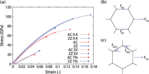
Figure 4. Fracture of: (a) a pristine AC graphene sheet with a diagonal length of 14.63 nm at 300 K; (b) a pristine ZZ graphene sheet with a diagonal length of 14.84 nm at 300 K; (c) an AC graphene sheet with a diagonal length of 14.63 nm at 300 K and a monovacancy defect at its centre; (d) a ZZ graphene sheet with a diagonal length of 14.84 nm at 300 K and a monovacancy defect at its centre; (e) a ZZ graphene sheet with a diagonal length of 14.84 nm at 300 K with 5.5% of the original atoms selected randomly and removed as vacancy defects; and (f) a ZZ graphene sheet with a diagonal length of 13.67 nm at 300 K with 5% of the original atoms being removed as vacancy defects and distributed uniformly.
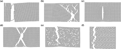
Figure 5. (Colour online) Results for (a) elastic modulus, (b) fracture stress and (c) fracture strain of AC and ZZ graphene sheets ( nm), varying with sheet temperature. In all graphs, the solid circles represent the AC direction while the inverted triangles represent the ZZ direction.
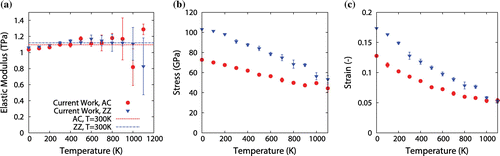
Table 2. Measured mechanical properties of pristine bulk graphene.
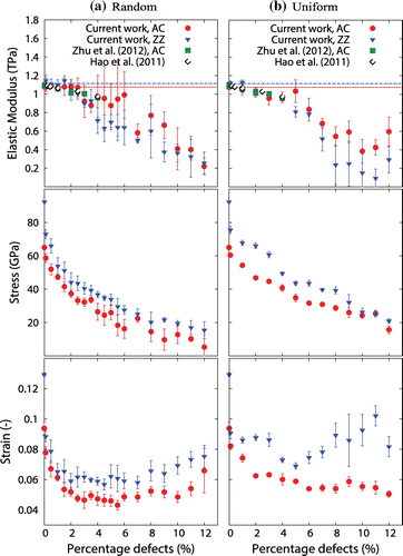
Figure 6. (Colour online) Graphs showing elastic modulus, fracture stress and fracture strain for AC- and ZZ-loaded graphene sheets at 300 K with increasing defect density distributed (a) randomly, and (b) uniformly. In all graphs, our MD results are represented by solid circles for the AC direction and inverted triangles for the ZZ direction, while dashed lines represent bulk mechanical properties.