Figures & data
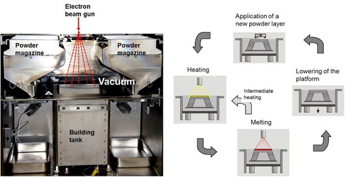
1 SEBM process. Left: Process chamber. Right: 4-step process for building one layer
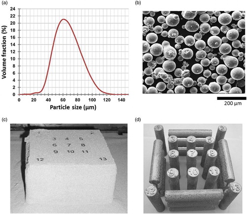
2 a Typical particle size distribution of a gas atomised powder (here: CMSX-4), b Ti–6Al–V4: SEM of the powder particles. Non-spherical particles, particle agglomerates and satellites are visible. c Sintered powder block (Ti–6Al–4V), d c after removing the powder by sand blasting with the same powder
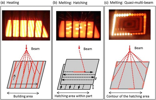
3 Heating and melting during SEBM. At the top: photograph during the process. At the bottom: schematic of the beam movement. a Heating by quasi-multi-beam scanning of the total building area with a defocused beam, b Melting by hatching, c Quasi-multi-beam contour melting by jumping from point to point
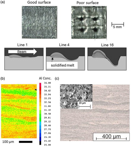
4 Evaporation effects: a Exemplary melt surfaces of 15 × 15 × 10 mm³ cubic samples. Left: good surface, right: poor surface with a characteristic pattern induced by material displacement, bottom: Simulation to illustrate the mechanism of melt displacement. The beam moves from left to right up to 16 times leaving behind a built-up area and a deep hole. b Element mapping showing the Al distribution in Ti–48Al–2Cr–2Nb, c Layered microstructure as built in Ti–48Al–2Cr–2Nb
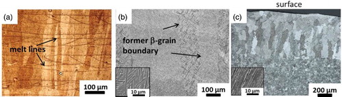
5 Grain structure of different materials processed by SEBM: a Pure copper,Citation12 b Ti–6Al–4V c Ti–48Al–2Nb–2Cr at the surfaceCitation13
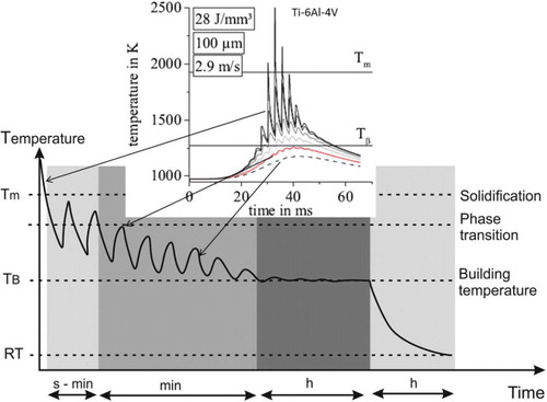
6 In-situ heat treatment during SEBM: Schematic of the temperature evolution at a fixed point of the component where the beam passes several times in each layer. A simulated temperature evolution at different depths (in steps of 100 µm) for Ti–6Al–4V is shown to visualise the time scale of temperature variation near the surface during and after melting
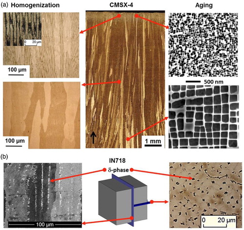
7 In-situ heat treatment during SEBM: a Nickel-base alloy CMSX-4 (schematic). Middle: Micrograph of the sample with elongated grains. Left: Homogenisation (LOM), Right: Aging of the γ’-particles (SEM) (see also Ref. Citation16), b Nickel-base alloy IN718: the niobium-rich δ-phase is precipitated in the interdendritic areas with columnar architecture
8 Distortion and surface roughness of a T-beam made of Ti–6Al–4V
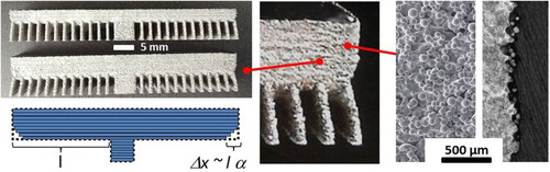
Table 1 SEBM materials
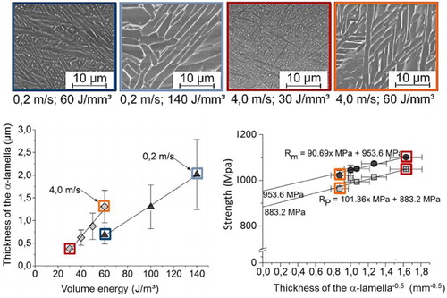
9 Influence of the building parameters on the microstructure and properties of Ti–6Al–4V. Top: Microstructure for different beam velocities and total energy input per volume. Bottom, left: Thickness of the α–lamella as a function of the volume energy. Bottom, right: Strength as a function of the α–lamella thickness (adapted from Ref. Citation28)
10 Influence of different processing strategies on the grain structure of IN718. SEM-micrograph showing a columnar grain structure a and an equiaxed grain structure b in a longitudinal section parallel to the building direction (for details see Ref. Citation25)
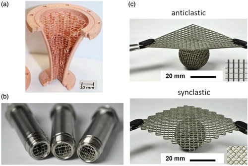
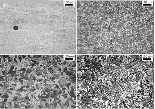
11 Typical small spherical defect in EBM γ-TiAl specimens a; as-built microstructure after EBM b; microstructure after HIP c; microstructure after thermal treatment d (courtesy of Ref. Citation56)
12 Cellular structures and materials. a Pure copper component with a cellular core, b Reactor (stainless steel 1.4404) for hydrogen release from perhydro-N-ethylcarbazole,Citation77 c Normal Ti–6Al–4V lattice structure (anticlastic) versus auxetic structure (synclastic) (adapted from Ref. Citation93)