2,261
Views
19
CrossRef citations to date
0
Altmetric
Original Articles

Pavement performance follow-up and evaluation of polymer-modified test sections

, , &
Pages 1474-1487 | Received 12 Oct 2017, Accepted 25 Jan 2018, Published online: 13 Feb 2018

Figures & data

Table 1. Description of test structures.

Figure 1. Test structure with layer thicknesses in mm.

Figure 1. Test structure with layer thicknesses in mm.

Table 2. Mix composition and properties of the binder.

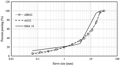
Figure 2. Grain size distribution of the surface, binder and base course mixes.

Figure 2. Grain size distribution of the surface, binder and base course mixes.

Figure 3. Master curves of (a) Dynamic shear modulus, (b) Phase angle of the surface course mixes SMA 16 with different binders at a reference temperature of 10°C.
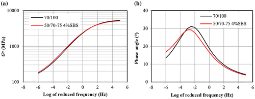
Figure 3. Master curves of (a) Dynamic shear modulus, (b) Phase angle of the surface course mixes SMA 16 with different binders at a reference temperature of 10°C.

Figure 4. Master curves of (a) Dynamic shear modulus, (b) Phase angle of the binder course mixes ABb 22 with different binders at a reference temperature of 10 °C.
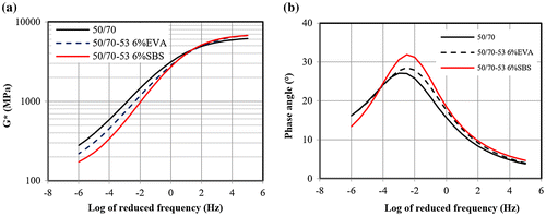
Figure 4. Master curves of (a) Dynamic shear modulus, (b) Phase angle of the binder course mixes ABb 22 with different binders at a reference temperature of 10 °C.

Figure 5. Master curves of (a) Shear modulus of upper base course, (b) Phase angle of upper base course mixes, (c) Shear modulus of lower base course and (d) Phase angle of lower base course, at a reference temperature of 10 °C.
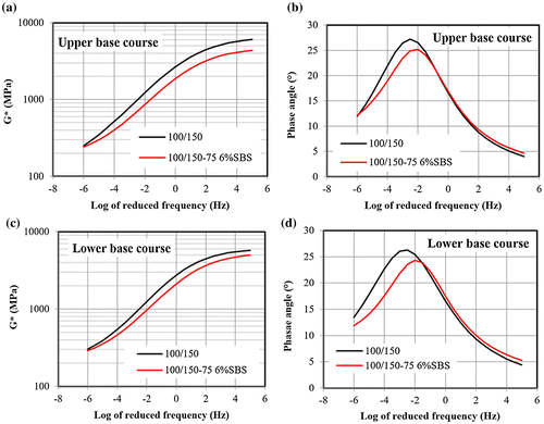
Figure 5. Master curves of (a) Shear modulus of upper base course, (b) Phase angle of upper base course mixes, (c) Shear modulus of lower base course and (d) Phase angle of lower base course, at a reference temperature of 10 °C.

Figure 6. Complex viscosity at peak phase angle; (a) surfacing (SMA 16), (b) binder course (ABb 22) and (c) and (d) upper and lower base courses (AG 22), respectively.
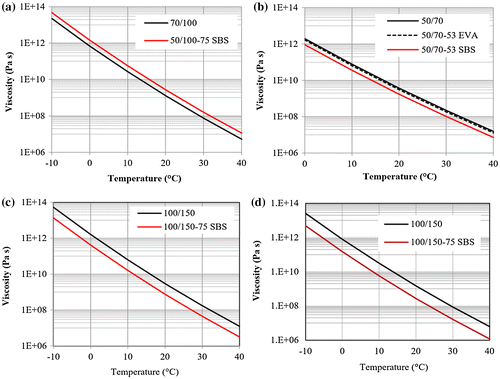
Figure 6. Complex viscosity at peak phase angle; (a) surfacing (SMA 16), (b) binder course (ABb 22) and (c) and (d) upper and lower base courses (AG 22), respectively.

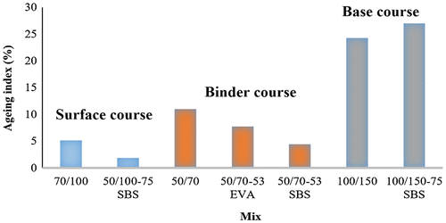
Figure 7. Ageing index at 10 °C.

Figure 7. Ageing index at 10 °C.

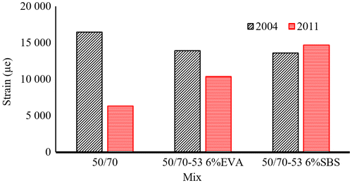
Figure 8. RLCT creep strain of the binder mixes from 2004 and 2011.

Figure 8. RLCT creep strain of the binder mixes from 2004 and 2011.

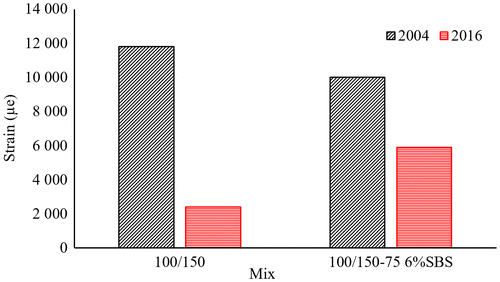
Figure 9. RLCT creep strain of base course mixes from 2004 and 2016.

Figure 9. RLCT creep strain of base course mixes from 2004 and 2016.

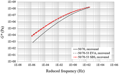
Figure 10. Master curves of the binders extracted from binder courses.

Figure 10. Master curves of the binders extracted from binder courses.

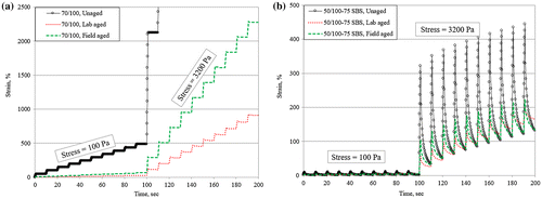
Figure 11. Examples of MSCR test at 60 °C for unmodified and SBS-modified binders.

Figure 11. Examples of MSCR test at 60 °C for unmodified and SBS-modified binders.

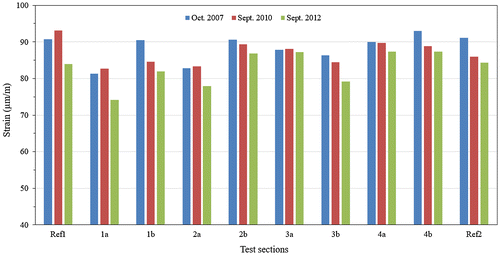
Figure 12. Estimated horizontal strain at the bottom of the bituminous layers adjusted to 10 °C.

Figure 12. Estimated horizontal strain at the bottom of the bituminous layers adjusted to 10 °C.

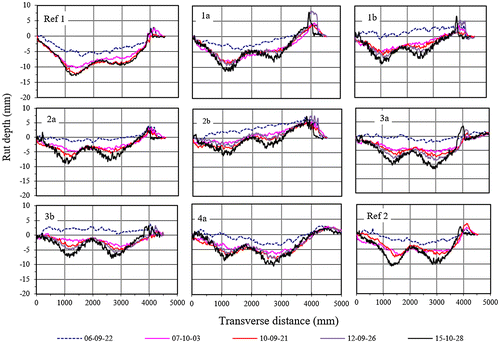
Figure 13. Transverse profiles of the test sections developed over time.

Figure 13. Transverse profiles of the test sections developed over time.

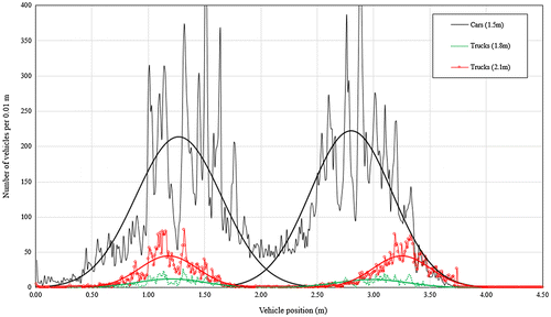
Figure 14. Distribution of lateral position of traffic at the test road motorway E6.

Figure 14. Distribution of lateral position of traffic at the test road motorway E6.

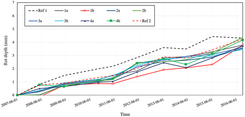
Figure 15. Average rut development in the left wheel track from RST measurements.

Figure 15. Average rut development in the left wheel track from RST measurements.

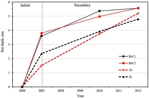
Figure 16. Impact of ageing on modified and unmodified mixes at initial and secondary zones.

Figure 16. Impact of ageing on modified and unmodified mixes at initial and secondary zones.

Figure 17. Laboratory-determined fatigue life relationships (a) and service lives of pavement structures based on estimated strains from FWD deflection measurements at 10 °C (b).
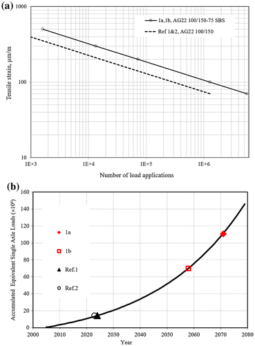
Figure 17. Laboratory-determined fatigue life relationships (a) and service lives of pavement structures based on estimated strains from FWD deflection measurements at 10 °C (b).
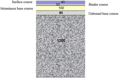
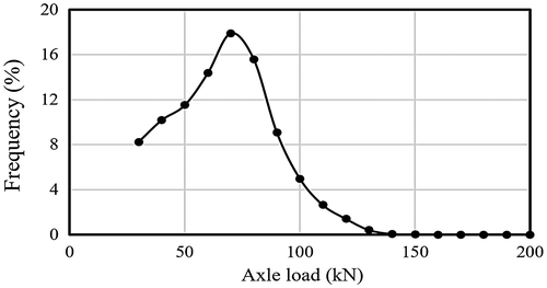
Figure 18. Axle load spectra of the selected WIM station.

Figure 18. Axle load spectra of the selected WIM station.

Table 3. Analysis parameters.

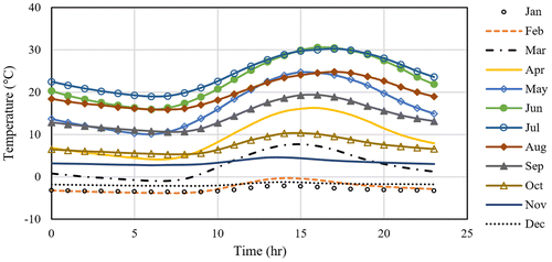
Figure 19. Monthly and hourly temperature variation at 2 cm below the surface.

Figure 19. Monthly and hourly temperature variation at 2 cm below the surface.

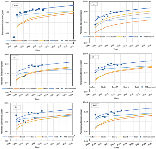
Figure 20. Measured and modelled permanent deformation of the pavement structures.

Figure 20. Measured and modelled permanent deformation of the pavement structures.