Figures & data
Figure 1. Geometry details for the impingement cooling system.
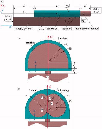
Figure 2. Sketch of racetrack-shaped hole.
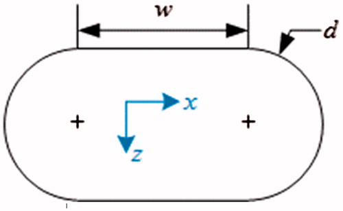
Table 1. Parameter details of the impingement
Table 2. Summary of test condition for present study
Figure 3. Comparison of experiment and simulation.
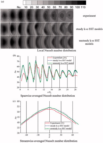
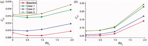
Figure 4. Difference of time-averaged Nusselt number and total pressure loss.
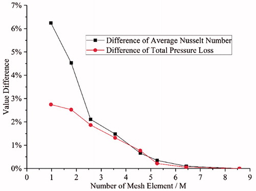
Figure 5. Schematic of a mesh system.
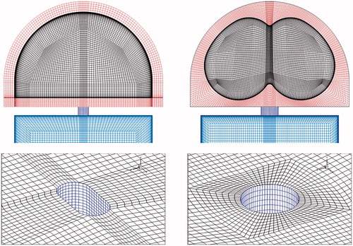
Figure 6. Nusselt number distributions for semi-cylinder channel at different Rotation numbers.
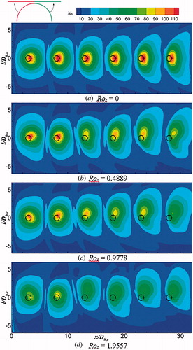
Figure 7. Sketch of velocities and body forces in a rotating impingement cooling system.
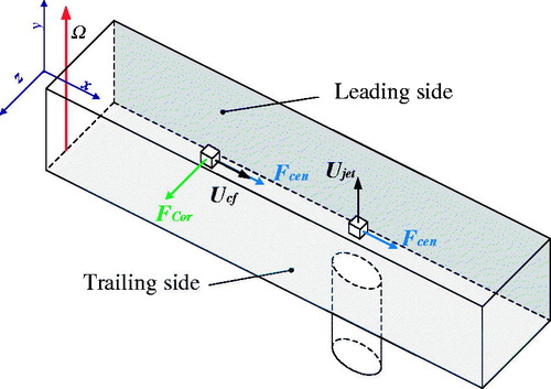
Figure 8. Average streamwise Nu number distribution of the baseline case.
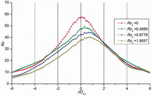
Figure 9. Nusselt number distributions for three cases at Ros = 0.9778.
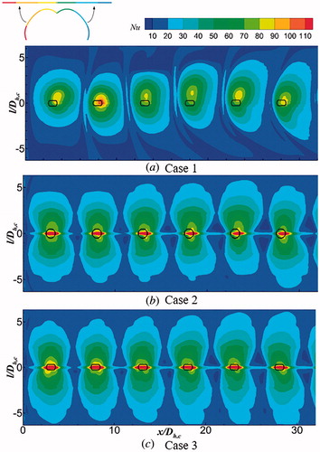
Figure 10. Streamwise averaged Nusselt number distribution at the stationary and rotating conditions.
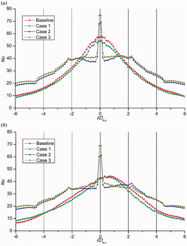
Figure 11. Temperature distributions on the outer solid surface.
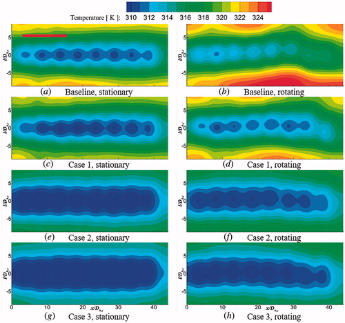
Figure 12. v/Ujet distribution on the symmetry plane for the baseline case.
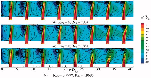
Figure 13. U/Ujet and temperature gradient distributions at two axial positions.
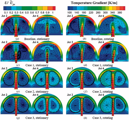
Figure 14. Turbulence kinetic energy distributions at Ros = 0.9778.
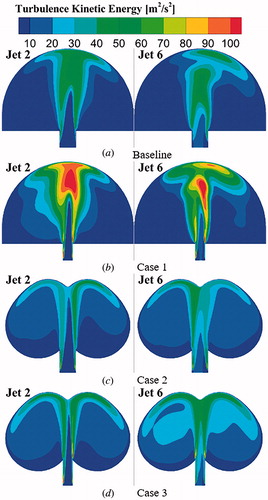
Figure 15. Averaged Nusselt number for four cases at Res = 7,854 and 19,635; Ros = 0 – 1. 9557.
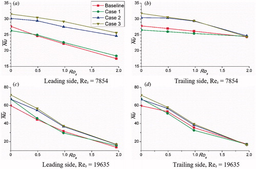
Figure 16. Total pressure drop ratio for four cases at Res = 7,854 and 19,635; Ros = 0 – 1. 9557.