Figures & data
Figure 1. Wedge duct and dimple configurations. (a) Wedge configurations, (b) dimple configurations, (c) protrusion configurations.
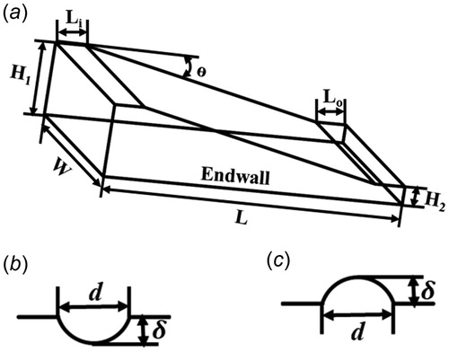
Figure 2. Pin fin arrangement and those with dimples/protrusions positions. (a) pin fin arrangement, (b) case 1, 4, (c) case 2, 5, (d) case 3, 6. Pin fins-the white circles, dimples/protrusions-filled circles.
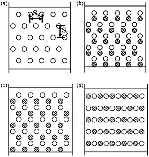
Figure 3. The schematic of the blade with dimples added between the pin fins at trailing edge.
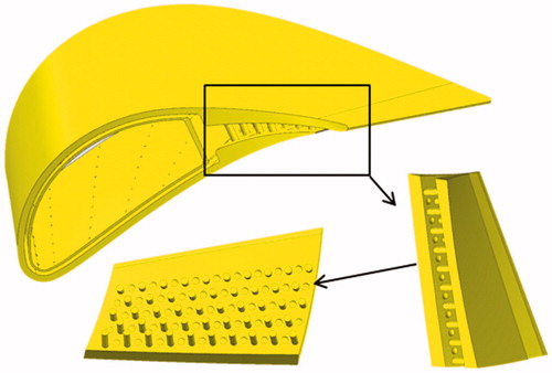
Table 1. Details of the different cases.
Figure 4. Boundary details of the conjugate heat transfer calculation.
Figure 5. Grids for wedge duct with pin fins and dimples (case 2). (a) 2D grids, (b) 3D grids.
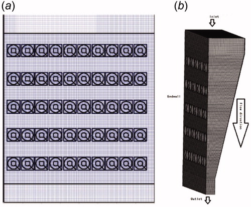
Figure 6. The fluid and solid domain grid for cooling blade.
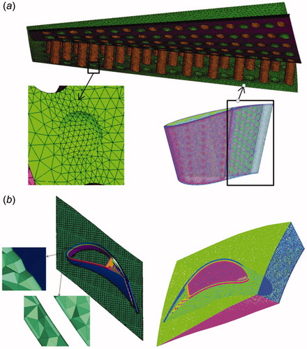
Figure 7. Mesh validation for blade calculation.
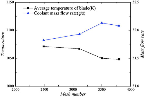
Figure 8. CFD validation.
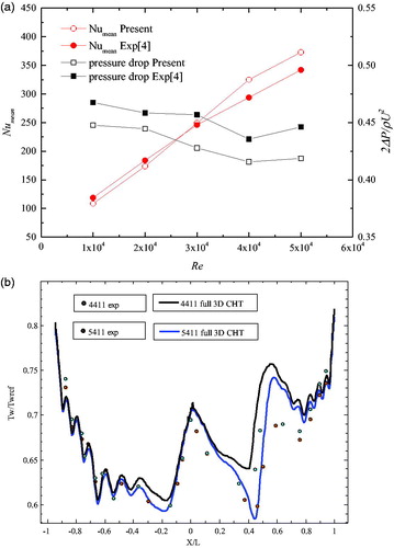
Table 2. Averaged Nusselt number for different cases.
Figure 9. Comparison of endwall heat flux distributions: (a) Case1, (b) Case2, (c) Case3, (d) Case4, (e) Case5, (f) Case6. Region A (black box).
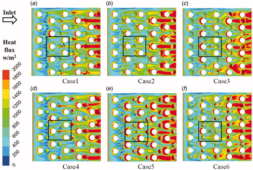
Figure 10. Comparison of streamlines in relevant regions. (a) Case1, (b) Case2, (c) Case3, (d) Case4, (e) Case5, (f) Case6.
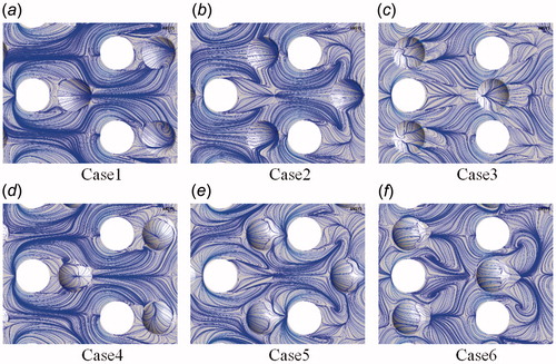
Figure 11. Comparison of TKE distribution in relevant regions. (a) Case1, (b) Case2, (c) Case3, (d) Case4, (e) Case5, (f) Case6.
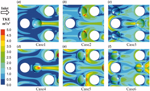
Figure 12. Comparison of heat flux distribution in relevant regions. (a) Case1, (b) Case2, (c) Case3, (d) Case4, (e) Case5, (f) Case6.
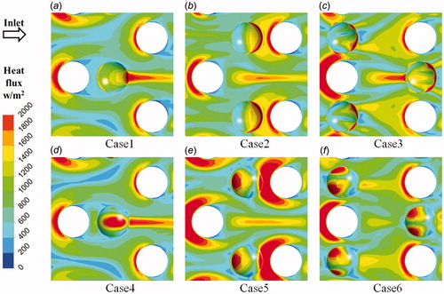
Table 3. Comparison of one-dimensional parameters.
Figure 13. Temperature (up) and wall heat flux (down) distributions on the pressure side inner face of blade trailing edge for different cases.
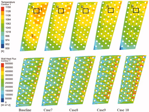
Figure 14. Streamlines, TKE, Wall heat flux and temperature distributions on the dimple of trailing edge pressure side.
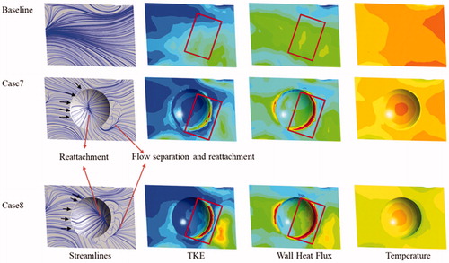
Figure 15. Streamlines, TKE, Wall heat flux and temperature distributions on the protrusion of trailing edge pressure side.
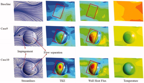
Figure 16. Streamlines, TKE, Wall heat flux and temperature comparisons between dimple and protrusion for δ/d = 0.3 of trailing edge pressure side.
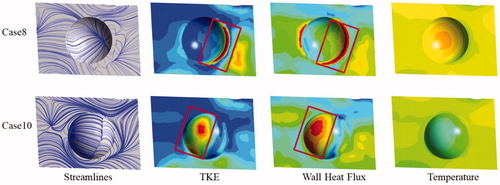
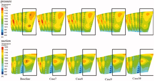
Figure 17. Temperature distributions on the blade surface pressure (upper) and suction (lower) side.