Figures & data
Figure 1. (a1-a6) the preparation process of PDMS/SGO@Conductive copper film. (b) the diagrammatic sketch of PS-TENG device. (c) the structural configuration of triboelectric pairs. (d) the picture of PDMS/SGO film. The SEM image of (e) PDMS/SGO film surface and (f) Nylon film surface.
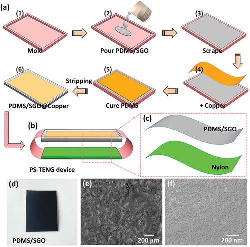
Figure 2. (A-d) the working principle of PS-TENG device.
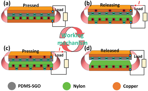
Figure 3. (a) the open-circuit voltage and (b) short-circuit current of PS-TENG under different force. (c) the open-circuit voltage and (d) short-circuit current of PS-TENG under mechanical frequency.
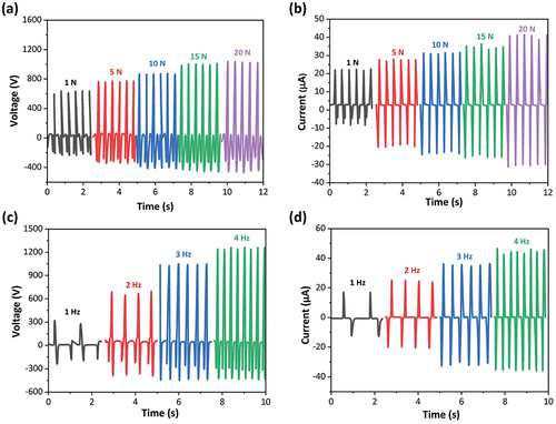
Figure 4. (a) the output voltage and current of PS-TENG with various resistances. (b) the output power of PS-TENG under different resistances. (c) the equivalent-circuit model of PS-TENG charging for capacitor. (d) the charging curves of PS-TENG charging for different capacitors.
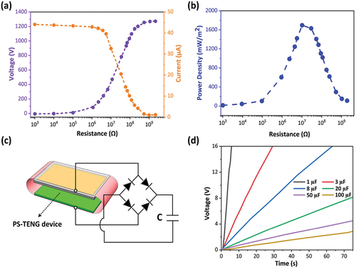
Figure 5. (a) the output voltage signal of PS-TENG when the athlete is in various motion postures, such as (a) jogging, (b) stomp, (c) jumping, (d) marking time, (e) running, and (f) walking. (g) reliability study of PS-TENG under prolonged continuous working conditions.
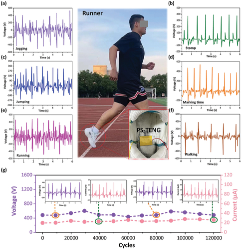
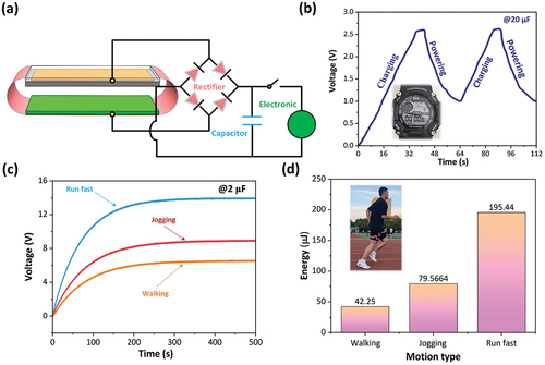
Figure 6. (a) the equivalent-circuit model of PS-TENG charging for electronic. (b) the charging/discharging curve of 20 µF capacitor for powering the electronic watch. (c) the charging curves of 2 µF capacitor under run fast, jogging, and walking. (d) Electric energy stored in 2 µF capacitor under different sports states of athletes, such as run fast, jogging, and walking.