Figures & data
Table 1. Welding parameter of fillet weld.
Figure 1. Hardness testing path of fillet weld.
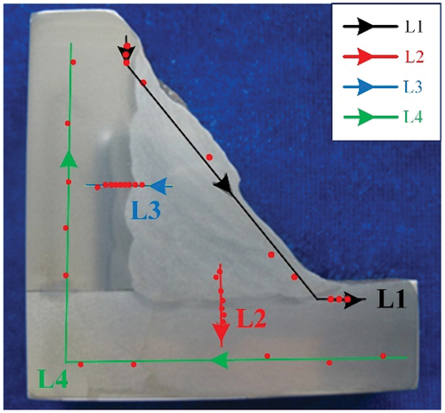
Figure 2. Finite element model.
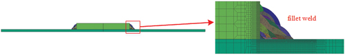
Table 2. Tensile properties of X80 pipe.
Figure 3. Impact mechanical properties.
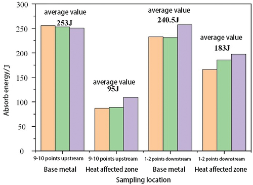
Table 3. Charpy impact test results of fillet welds.
Figure 4. Vickers hardness of fillet weld.
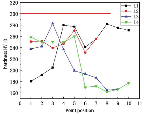
Figure 5. Cross section of fillet weld.
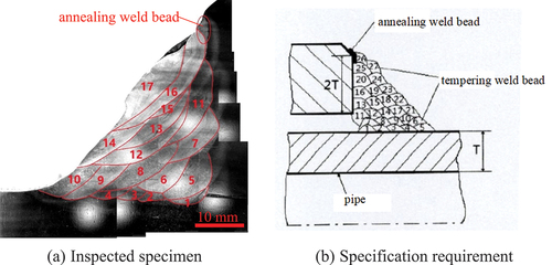
Figure 6. Thickness and width of weld bead.
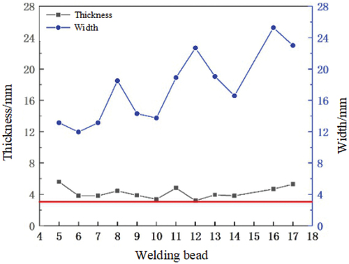
Figure 7. Metallurgical microstructure of pipe and sleeve.
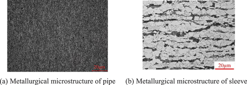
Figure 8. Metallurgical microstructure of fillet weld.
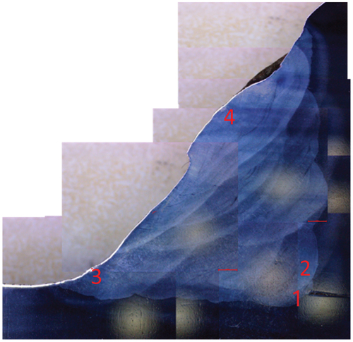
Figure 9. Metallographic morphology of location 1 and location 2.
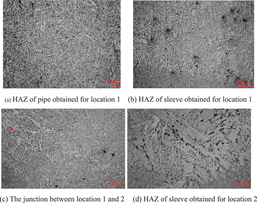
Figure 10. Metallographic morphology of location 3 and location 4.
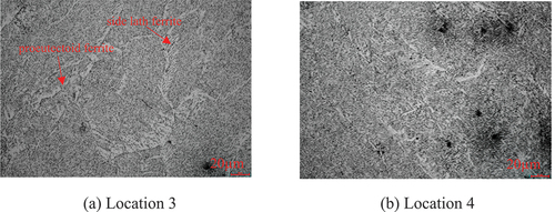
Figure 11. Sampling position and macrostructure of the transverse crack.
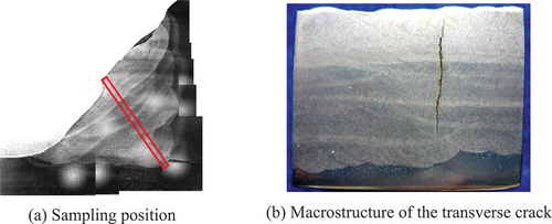
Figure 12. Propagation morphology of transverse cracks.
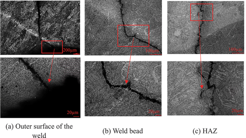
Figure 13. Crack terminates in the HAZ.
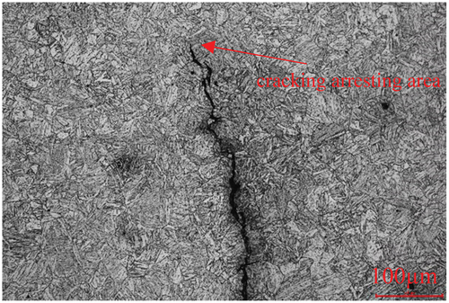
Figure 14. EBSD characterization results of crack.
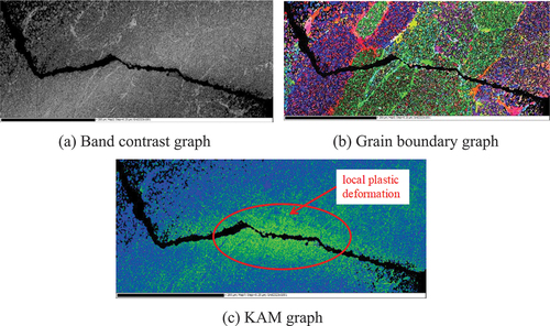
Figure 15. The morphology of fracture surface before pickling.
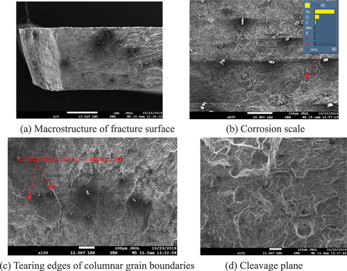
Figure 16. The morphology of fracture surface after pickling.
Figure 17. Residual stress nephogram after welding.
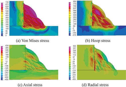
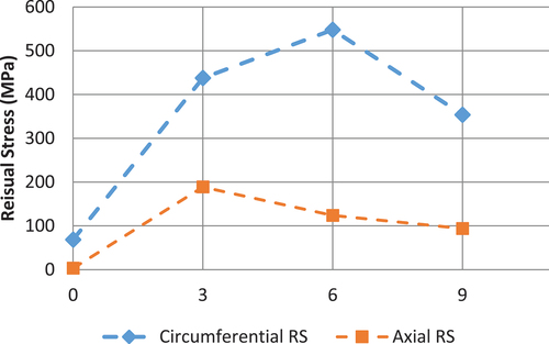
Figure 18. Residual stress test results of fillet weld.