Figures & data
Figure 1 Static and dynamic yield stress (from[Citation15]).
![Figure 1 Static and dynamic yield stress (from[Citation15]).](/cms/asset/2ad3cd81-ffa5-4264-9f6f-6f4626b171fc/ljfp_a_331017_o_f0001g.gif)
Figure 2 Typical strain-time curves obtained during yield stress measurement by the creep-recovery test (from[Citation1]).
![Figure 2 Typical strain-time curves obtained during yield stress measurement by the creep-recovery test (from[Citation1]).](/cms/asset/95c9531a-14cc-4139-9940-854e96852600/ljfp_a_331017_o_f0002g.gif)
Figure 3 Stress ramp curve for margarine (from[Citation21]).
![Figure 3 Stress ramp curve for margarine (from[Citation21]).](/cms/asset/c767036e-302f-40f1-b0e3-066d3ec950cd/ljfp_a_331017_o_f0003g.gif)
Figure 4 Illustration of a cone penetrometer assembly (from[Citation25]).
![Figure 4 Illustration of a cone penetrometer assembly (from[Citation25]).](/cms/asset/a595c905-3542-4b62-9bd4-e1cf5695334e/ljfp_a_331017_o_f0004g.gif)
Figure 5 Dynamic oscillatory measurement (from[Citation15]).
![Figure 5 Dynamic oscillatory measurement (from[Citation15]).](/cms/asset/78cd91d6-1276-4fcc-8f0c-629b1a5cec16/ljfp_a_331017_o_f0005g.gif)
Figure 6 Schematic of the flow in an inclined plate (from[Citation28]).
![Figure 6 Schematic of the flow in an inclined plate (from[Citation28]).](/cms/asset/b69eaa94-1773-4770-936b-d49e1a527b62/ljfp_a_331017_o_f0006g.gif)
Figure 7 Illustration of post-withdrawal drainage process (from[Citation29]).
![Figure 7 Illustration of post-withdrawal drainage process (from[Citation29]).](/cms/asset/65b4a900-cd31-4e20-a15b-32bc2df0cbc0/ljfp_a_331017_o_f0007g.gif)
Figure 8 Schematic of a typical four-bladed vane (left) and how it is used during measurement (right). [H = vane height, D = vane diameter, DT = container diameter, Ω = angular velocity, (a): immersed in the sample (Z1 and Z2 height of sample above and below the vane, respectively); (b): top surface in level with sample] (from[Citation25]).
![Figure 8 Schematic of a typical four-bladed vane (left) and how it is used during measurement (right). [H = vane height, D = vane diameter, DT = container diameter, Ω = angular velocity, (a): immersed in the sample (Z1 and Z2 height of sample above and below the vane, respectively); (b): top surface in level with sample] (from[Citation25]).](/cms/asset/9199352f-05a4-4204-94b9-980f5e4eb8e6/ljfp_a_331017_o_f0008g.gif)
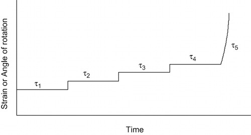
Figure 9 Typical response curve for yield stress measurement with the vane method under controlled shear-stress mode. Shear stress τ1 through τ5 are applied each for certain duration.

Figure 10 Typical torque versus time response curve for yield stress measurement with the vane method under controlled shear-rate mode (from[Citation25]).
![Figure 10 Typical torque versus time response curve for yield stress measurement with the vane method under controlled shear-rate mode (from[Citation25]).](/cms/asset/08500fab-5bc9-447d-a6ad-f7600370585d/ljfp_a_331017_o_f0010g.gif)
Figure 11 Geometry of squeezing flow test under constant area and constant volume (from[Citation38]).
![Figure 11 Geometry of squeezing flow test under constant area and constant volume (from[Citation38]).](/cms/asset/95c677c2-0b94-48c7-b1c7-d038f139ae73/ljfp_a_331017_o_f0011g.gif)
Figure 12 Schematic of imperfect squeezing flow apparatus (from[Citation40]).
![Figure 12 Schematic of imperfect squeezing flow apparatus (from[Citation40]).](/cms/asset/82b49526-69ed-44bc-b8ad-6a864c5aba92/ljfp_a_331017_o_f0012g.gif)
Figure 13 Typical profile in squeeze flow testing for two types of fluids: Newtonian (full line) and Bingham (dashed line) (from[Citation36]).
![Figure 13 Typical profile in squeeze flow testing for two types of fluids: Newtonian (full line) and Bingham (dashed line) (from[Citation36]).](/cms/asset/02916a4f-e5cb-44bd-9c52-694fe1ba6d53/ljfp_a_331017_o_f0013g.gif)
Figure 14 Picture of the dual sample well UW Meltmeter (Left) and sample formed with the lever in the down position (from[Citation21]).
![Figure 14 Picture of the dual sample well UW Meltmeter (Left) and sample formed with the lever in the down position (from[Citation21]).](/cms/asset/c5640bec-d5b0-4dd8-b79f-b1a09fe42059/ljfp_a_331017_o_f0014g.jpg)
Figure 15 Illustration of the plate method in measuring yield stress (from[Citation28]).
![Figure 15 Illustration of the plate method in measuring yield stress (from[Citation28]).](/cms/asset/cd10989d-9043-493b-ad97-421faceb19d5/ljfp_a_331017_o_f0015g.gif)
Figure 16 (A) Typical response of the plate method; and (B) yield stress obtained from extrapolation of measured shear stress versus platform speed (from[Citation28]).
![Figure 16 (A) Typical response of the plate method; and (B) yield stress obtained from extrapolation of measured shear stress versus platform speed (from[Citation28]).](/cms/asset/f318becb-3c67-4409-be58-f5c39166e8c9/ljfp_a_331017_o_f0016g.gif)
Figure 17 (A) Schematic diagram of the slotted-plate device; and (B) typical time response curve (from[Citation45]).
![Figure 17 (A) Schematic diagram of the slotted-plate device; and (B) typical time response curve (from[Citation45]).](/cms/asset/b0783024-01fd-48a1-a2ee-f73dabfb21bc/ljfp_a_331017_o_f0017g.gif)
Figure 18 Schematic diagram of the initial and final state of stress distribution (from[Citation22]).
![Figure 18 Schematic diagram of the initial and final state of stress distribution (from[Citation22]).](/cms/asset/fc650fad-e2dc-4240-9245-b3bab6e47889/ljfp_a_331017_o_f0018g.gif)
Figure 19 Schematic diagram of the slump test (from[Citation22]).
![Figure 19 Schematic diagram of the slump test (from[Citation22]).](/cms/asset/dba7ca4a-3261-4e26-b10d-80857db12497/ljfp_a_331017_o_f0019g.gif)
Figure 20 Schematic diagram of the MRI apparatus integrated into tube viscometer (from[Citation54]).
![Figure 20 Schematic diagram of the MRI apparatus integrated into tube viscometer (from[Citation54]).](/cms/asset/54394a5c-a017-4fb3-9890-101a49f30e2d/ljfp_a_331017_o_f0020g.gif)
Figure 21 (A) Structure of dry; and (B) wet foams (on Left). Schematic diagram of the solid-like and liquid-like behaviors of foams (on right) (from[Citation64]).
![Figure 21 (A) Structure of dry; and (B) wet foams (on Left). Schematic diagram of the solid-like and liquid-like behaviors of foams (on right) (from[Citation64]).](/cms/asset/32882d19-1498-414f-99a2-2614913f8469/ljfp_a_331017_o_f0021g.jpg)
Figure 22 Schematic of chocolate coating application with enrobing technology (from[Citation54]).
![Figure 22 Schematic of chocolate coating application with enrobing technology (from[Citation54]).](/cms/asset/088dcd6f-ad7a-41e1-8221-ff6abcb2e6d4/ljfp_a_331017_o_f0022g.gif)
Figure 23 Spreadability map for elastoplastic foods: (M) margarine spread; (PCS) processed cheese spread; (PB) peanut butter; (RFPB) reduced fat peanut butter; (GJ) grape jelly; (CC) cream cheese; (FCC) free cream cheese; (B) touch of butter; (FY) fat free plain yogurt; (SC) sour cream; (NSC) non-fat sour cream; (WT) whipped cream; and (FWT) fat free whipped cream (from[Citation74]).
![Figure 23 Spreadability map for elastoplastic foods: (M) margarine spread; (PCS) processed cheese spread; (PB) peanut butter; (RFPB) reduced fat peanut butter; (GJ) grape jelly; (CC) cream cheese; (FCC) free cream cheese; (B) touch of butter; (FY) fat free plain yogurt; (SC) sour cream; (NSC) non-fat sour cream; (WT) whipped cream; and (FWT) fat free whipped cream (from[Citation74]).](/cms/asset/14ab41ee-d46f-44b4-9004-d9db99dba9d3/ljfp_a_331017_o_f0023g.gif)