Figures & data
Figure 1. Automatic hardness testing equipment: (a) automatic hardness testing machine (Struers DuraScan 80) used in the present work; (b) large-scale Vickers Hardness tester with CNC stage.
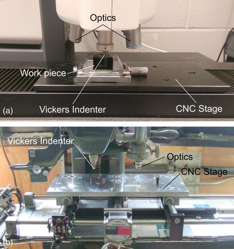
Figure 2. A simple example of workpiece set-up and refinement process. Light graphics indicate estimated indentation region, while dark show the actual measurement. (a) Example workpiece/ROI outline with reference indents prior (i) to meshing and after (ii). (b) Initial triangular array and estimated plastically affected zones (i), after first hardness assessment (ii), updated map (iii), subsequent map with overlap of plastic zones identified (iv).
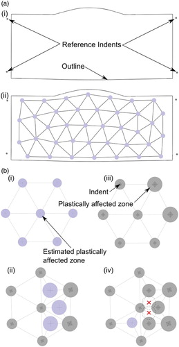
Figure 3. A flow diagram describing the initial mesh generation, indentation and further refinement of hardness maps from workpieces using the technique described.
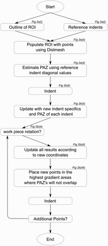
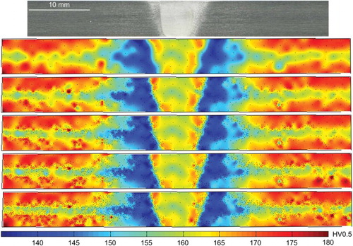
Figure 4. DMW macrograph and hardness maps. Manufactured from Alloy 82 Clad SA508–4N low-alloy steel to 316LN Stainless Steel via a filler of Alloy 82. This workpiece was indented with 1937 indents; 1337 initial indents and 2 refinements of 300 indents each using a load of 1 kg. Showing the first (top), second and third maps (middle), black dots show indent locations. Also shown is a map generated without refinement, approximating an RSD comprising 1937 indents (bottom).
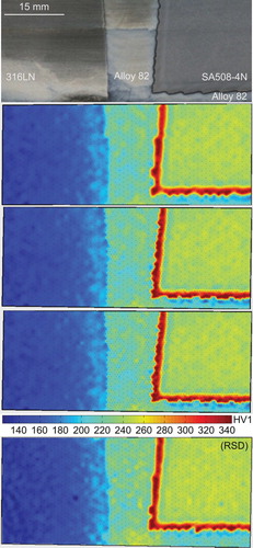
Figure 5. NeT TG6 SMW macrograph and hardness maps. This cross-section was extracted from 12-mm thick Alloy 600 plate containing three superimposed Alloy 82 weld passes deposited via a TIG process. Map shows a total 928 indents (253 initial indents and 9 refinements of 75 indents each) using a load of 0.5 kg. The first, fifth and ninth maps are shown, black dots indicate indent locations. Subplots on the right show line scans comprising indents between the lines shown on the left, with symbols showing indents, and lines showing an interpolated spline.
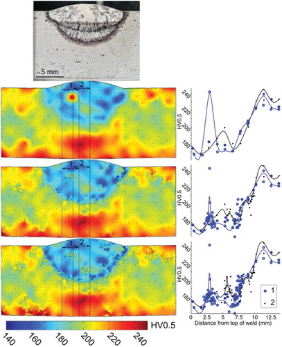
Figure 6. Aluminium FSW macrograph and hardness maps. A 6-mm thick AA7010-T7651 aluminium alloy workpiece was processed via autogenous FSW with a pin rotation speed of 1500 rev min−1 and a travel speed of 200 mm−1. This workpiece was indented with 1436 indents (236 initial indents and 8 refinements of 150 indents each) using a load of 0.5 kg. The first, third, fifth, seventh and ninth levels of refinement are shown. Black dots show indent locations.