Figures & data
Figure 1. Parachute–forebody structure.
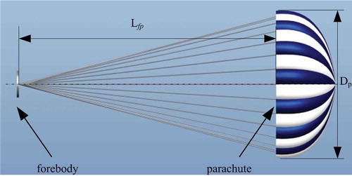
Figure 2. Position and displacement of the parachute.
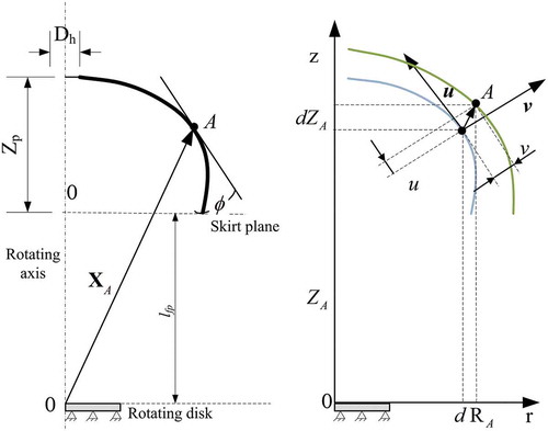
Figure 3. Undeformed Gore profile of a round parachute.
Figure 4. ALE formulation and mesh moving.
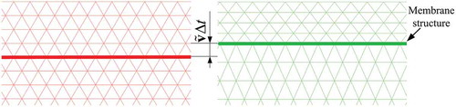
Figure 5. Time history of the vent hole parachute force.
Figure 6. Parachute inflation process.
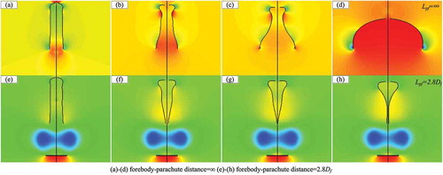
Figure 7. Opening shock with different free stream velocity.
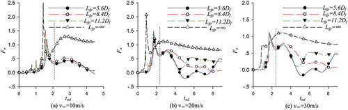
Figure 8. Variant of the flow topology according to time.
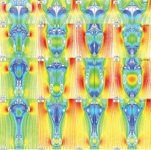
Figure 9. Structure of the forebody.
Figure 10. Flow topology of a single forebody.
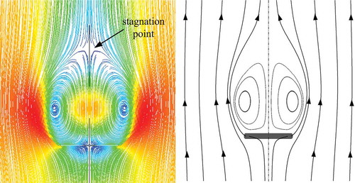
Figure 11. Pressure and velocity distribution with different forebody radius.
Figure 12. Pressure and velocity distribution with different velocity.
Figure 13. Fluid topology of a single parachute.
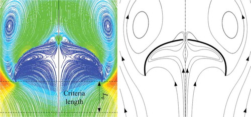
Figure 14. Velocity and pressure distribution along the parachute.
Figure 15. Experimental and CFD velocity distributions behind forebody.
Figure 16. Drag loss vs. forebody radius.
Figure 17. Drag loss vs. forebody–parachute distance.
Figure 18. Stream path with different forebody–parachute distance.
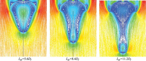
Figure 19. Flow topology with different forebody–parachute distance.