
Figures & data
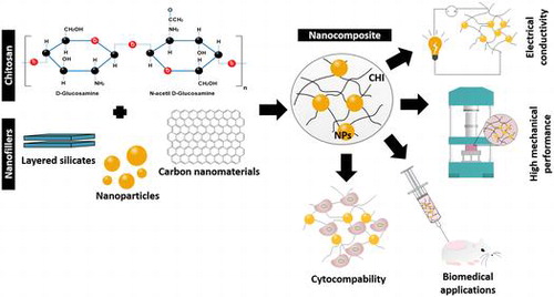
Figure 1. Main biomedical applications of chitosan nanocomposites.
Figure 2. Representation of the basic units (a) Si-O tetrahedron and Al-O or Al-O octahedron present on the clay minerals [Citation43]. (b) Representation of the different structures resulted from different clay dispersion in the polymeric matrix. (i) Tactoid structures, (ii) intercalated structures and (iii) exfoliated structures [Citation39].
![Figure 2. Representation of the basic units (a) Si-O tetrahedron and Al-O or Al-O octahedron present on the clay minerals [Citation43]. (b) Representation of the different structures resulted from different clay dispersion in the polymeric matrix. (i) Tactoid structures, (ii) intercalated structures and (iii) exfoliated structures [Citation39].](/cms/asset/41b6f646-154e-4a10-99f2-306cfe737b79/tsta_a_1229104_f0002_oc.gif)
Figure 3. Schematic representation of (a) graphene and (b) graphene oxide sheet [Citation86].
![Figure 3. Schematic representation of (a) graphene and (b) graphene oxide sheet [Citation86].](/cms/asset/049ed06e-4d53-458b-92cf-ed53cdd996e9/tsta_a_1229104_f0003_b.gif)
Table 1. Overview of CHI nanocomposites with different fillers.
Figure 4. (a) Schematic representation of the procedure to obtain a membrane/film using the solvent casting method. (b) Comparison between the surface of a (i) CHI membrane and (ii) CHI/bioactive glass membrane.[Citation115]
![Figure 4. (a) Schematic representation of the procedure to obtain a membrane/film using the solvent casting method. (b) Comparison between the surface of a (i) CHI membrane and (ii) CHI/bioactive glass membrane.[Citation115]](/cms/asset/f26fa2d9-601a-444e-9158-6f1f1e831c1c/tsta_a_1229104_f0004_oc.gif)
Figure 5. Representation of (a) three main LbL methods: (i) dip coating; (ii) spin coating and (iii) spray coating; and (b) image of a chitosan/alginate free-standing membrane, where (i) represents the membrane obtained by dip coating a polypropylene substrate after 100 cycles and (ii) its respective cross-section scanning electron microscopy (SEM) picture.[Citation129]
![Figure 5. Representation of (a) three main LbL methods: (i) dip coating; (ii) spin coating and (iii) spray coating; and (b) image of a chitosan/alginate free-standing membrane, where (i) represents the membrane obtained by dip coating a polypropylene substrate after 100 cycles and (ii) its respective cross-section scanning electron microscopy (SEM) picture.[Citation129]](/cms/asset/fb89cb9d-c23d-4f72-bbe6-ae82ecdacaed/tsta_a_1229104_f0005_oc.gif)
Figure 6. Schematic illustration of the different structures resulted from the different building blocks and substrates used in the LbL process.[Citation130]
![Figure 6. Schematic illustration of the different structures resulted from the different building blocks and substrates used in the LbL process.[Citation130]](/cms/asset/eb550909-46db-4f31-bb37-e08d675dbefa/tsta_a_1229104_f0006_oc.gif)
Figure 7. (a) Representation of the different electrospinning approaches, namely (i) wet–dry spinning, (ii) wet–wet spinning and (iii) co-axial electrospinning. (b) Representation of a (i) macroscopic electrospun chitosan fiber mat and (ii) chitosan/hydroxyapatite nanoparticles fibers morphology obtained by SEM with respective insert image at lower magnification.[Citation136]
![Figure 7. (a) Representation of the different electrospinning approaches, namely (i) wet–dry spinning, (ii) wet–wet spinning and (iii) co-axial electrospinning. (b) Representation of a (i) macroscopic electrospun chitosan fiber mat and (ii) chitosan/hydroxyapatite nanoparticles fibers morphology obtained by SEM with respective insert image at lower magnification.[Citation136]](/cms/asset/91367e45-96a8-4927-a3c6-bb11680a7857/tsta_a_1229104_f0007_oc.gif)
Figure 8. Representation of a possible application of CHI nanocomposite for bone regeneration. CHI/BG-NPs scaffolds were used to fill the pig femur bone defect when this was hydrated.[Citation148]
![Figure 8. Representation of a possible application of CHI nanocomposite for bone regeneration. CHI/BG-NPs scaffolds were used to fill the pig femur bone defect when this was hydrated.[Citation148]](/cms/asset/7e27e884-4933-4148-93b3-a929647577a6/tsta_a_1229104_f0008_oc.gif)