2,909
Views
11
CrossRef citations to date
0
Altmetric
Bio-inspired and biomedical materials

Controlled Fab installation onto polymeric micelle nanoparticles for tuned bioactivity

, , , , , , , & show all
Pages 666-680 | Received 30 Jun 2017, Accepted 18 Aug 2017, Published online: 20 Sep 2017

Figures & data

Figure 1. Mass spectrometry analysis of 1C1 Fab before and after conjugating with phenyl maleimide-PEG-DBCO cross-linkers with different PEG lengths. Left panel: intact spectra, right panel: reduced spectra.
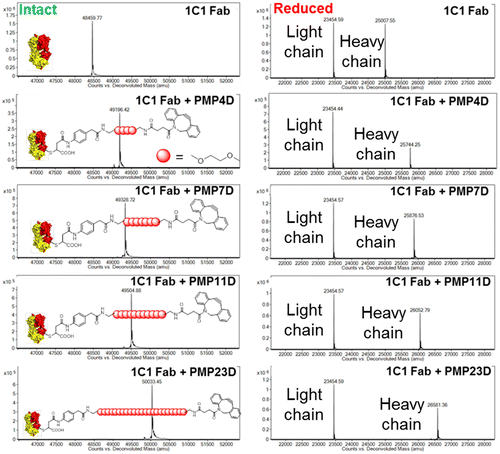
Figure 1. Mass spectrometry analysis of 1C1 Fab before and after conjugating with phenyl maleimide-PEG-DBCO cross-linkers with different PEG lengths. Left panel: intact spectra, right panel: reduced spectra.

Figure 2. Fab content in nanoparticle-Fab conjugates prepared using PMP4D, PMP7D, PMP11D and PMP23D bifunctional PEG linkers at Fab-linker/azide feed molar ratios of 0.1, 0.5, 1, 2, 4 and 8 during the conjugation reaction. The theoretical maximum is set as 10 (dashed line) based on the polymer association number of each nanoparticle.
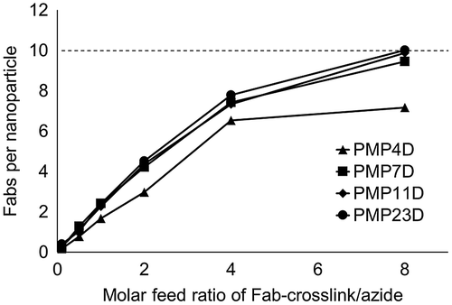
Figure 2. Fab content in nanoparticle-Fab conjugates prepared using PMP4D, PMP7D, PMP11D and PMP23D bifunctional PEG linkers at Fab-linker/azide feed molar ratios of 0.1, 0.5, 1, 2, 4 and 8 during the conjugation reaction. The theoretical maximum is set as 10 (dashed line) based on the polymer association number of each nanoparticle.

Figure 3. (A) Schematic overview of experiment to determine Fab- and unreacted azide-content by optical absorption. Fab content was determined by A280 measurement, whereas azide content was determined by A647 measurement after backfilling with Alexa Fluor 674-DBCO (A647). (B-D) UV-vis absorbance spectra of (B) unmodified micelles, (C) Fab-linker reacted micelles, and (D) Fab-linker and Alexa Fluor 647-DBCO reacted micelles.
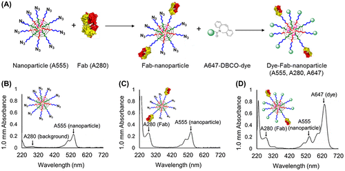
Figure 3. (A) Schematic overview of experiment to determine Fab- and unreacted azide-content by optical absorption. Fab content was determined by A280 measurement, whereas azide content was determined by A647 measurement after backfilling with Alexa Fluor 674-DBCO (A647). (B-D) UV-vis absorbance spectra of (B) unmodified micelles, (C) Fab-linker reacted micelles, and (D) Fab-linker and Alexa Fluor 647-DBCO reacted micelles.

Figure 4. Fab/NP and Dyes/NP conjugation efficiency using different bifunctional PEG linker (PMP4D, PMP7D, PMP11D and PMP23D) at Fab/azide feed molar ratio 2.
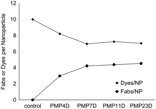
Figure 4. Fab/NP and Dyes/NP conjugation efficiency using different bifunctional PEG linker (PMP4D, PMP7D, PMP11D and PMP23D) at Fab/azide feed molar ratio 2.

Table 1. Z-average diameter and PDI of micelles.

Figure 5. Z-average diameter of unconjugated micelles (blue), Fab-installed micelles at a Fab/azide molar ratio of 2 (red) and Fab-installed micelles at a Fab/azide molar ratio of 8 (green) prepared using Fab-cross-linkers containing PMP4D, PMP7D, PMP11D or PMP23D heterobifunctional linkers.
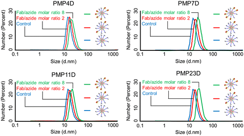
Figure 5. Z-average diameter of unconjugated micelles (blue), Fab-installed micelles at a Fab/azide molar ratio of 2 (red) and Fab-installed micelles at a Fab/azide molar ratio of 8 (green) prepared using Fab-cross-linkers containing PMP4D, PMP7D, PMP11D or PMP23D heterobifunctional linkers.

Table 2. Characterization of SN38-loaded micelles (SN38/m).

Figure 6. (A) Fluorescence microscopy images of PC3 cells (blue) after 10 min treatment of Cy5-labeled SN38-loaded micelles (red) installed with 1C1 Fab-linkers prepared with PEG4 or PEG23 cross-linkers. (B) Average Cy5 fluorescence intensity of each cell normalized to bare micelles. (C) Fluorescence microscopy images of PC3 cells (blue) after 6 h incubation with Cy5-labeled SN38-loaded micelles (red) installed with 1C1 Fabs having cross-linkers containing 4 or 23 units of PEG. (D) Average Cy5 fluorescence intensity of each cell normalized to bare micelles. Cell nuclei were stained with Hoechst (blue). Scale bar: 50 μm. In (B) and (D), data are shown as average ± standard deviation (SD) from four images taken in random fields and compared with Tukey-Kramer test. ** p < 0.01; n.s.: not significant.
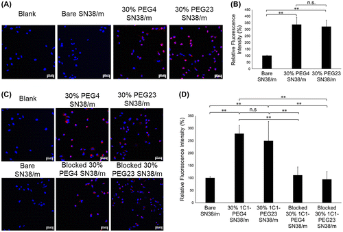
Figure 6. (A) Fluorescence microscopy images of PC3 cells (blue) after 10 min treatment of Cy5-labeled SN38-loaded micelles (red) installed with 1C1 Fab-linkers prepared with PEG4 or PEG23 cross-linkers. (B) Average Cy5 fluorescence intensity of each cell normalized to bare micelles. (C) Fluorescence microscopy images of PC3 cells (blue) after 6 h incubation with Cy5-labeled SN38-loaded micelles (red) installed with 1C1 Fabs having cross-linkers containing 4 or 23 units of PEG. (D) Average Cy5 fluorescence intensity of each cell normalized to bare micelles. Cell nuclei were stained with Hoechst (blue). Scale bar: 50 μm. In (B) and (D), data are shown as average ± standard deviation (SD) from four images taken in random fields and compared with Tukey-Kramer test. ** p < 0.01; n.s.: not significant.

Figure 7. In vitro cytotoxicity of irinotecan, bare SN-38/m,30% 1C1-PEG4- and 30% 1C1-PEG23-SN38/m against PC3 cells after (A) 24, (B) 48 and (C) 72 h incubation. Data are shown as average ± SD from four experiments.
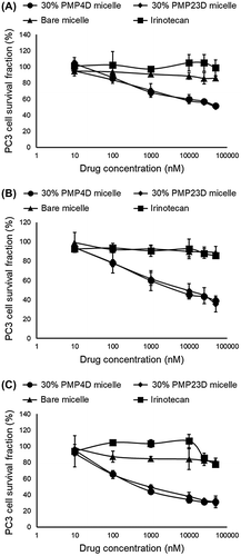
Figure 7. In vitro cytotoxicity of irinotecan, bare SN-38/m,30% 1C1-PEG4- and 30% 1C1-PEG23-SN38/m against PC3 cells after (A) 24, (B) 48 and (C) 72 h incubation. Data are shown as average ± SD from four experiments.

Table 3. Fifty-percent in vitro inhibitory concentration (IC50) values of irinotecan and SN38-loaded micelles (SN38/m) obtained after 6 h drug exposure and 24, 48 and 72 h post-incubation.

Figure 8. (A) Fluorescence microscopy images of PC3 cells (blue) after 10 min treatment of Cy5-labeled SN38-loaded micelles (red) installed with 30% or 60% 1C1 Fabs-linker prepared with PEG23 cross-linker. Cells nuclei were stained with Hoechst (blue). Scale bar: 50 μm. (B) Average fluorescence intensity of each cell normalized to bare micelles. Data are shown as average ± SD from four different images, and compared with Tukey-Kramer test. * p < 0.05; ** p < 0.01; n.s.: not significant.
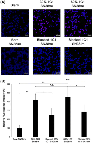
Figure 8. (A) Fluorescence microscopy images of PC3 cells (blue) after 10 min treatment of Cy5-labeled SN38-loaded micelles (red) installed with 30% or 60% 1C1 Fabs-linker prepared with PEG23 cross-linker. Cells nuclei were stained with Hoechst (blue). Scale bar: 50 μm. (B) Average fluorescence intensity of each cell normalized to bare micelles. Data are shown as average ± SD from four different images, and compared with Tukey-Kramer test. * p < 0.05; ** p < 0.01; n.s.: not significant.
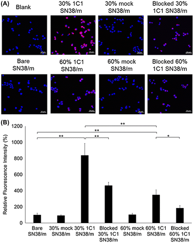
Figure 9. (A) Fluorescence microscopy images of PC3 cells (blue) after 6 h treatment of Cy5-labeled SN38-loaded micelles (red) installed with 30% or 60% 1C1 Fabs having cross-linkers containing 23 units of PEG. Cell nuclei were stained with Hoechst (blue). Scale bar: 50 μm. (B) Average fluorescence intensity of each cell normalized to bare micelles. Data are shown as average ± SD from four different images, and compared with Tukey-Kramer test. * p < 0.05; ** p < 0.01; n.s.: not significant.

Figure 9. (A) Fluorescence microscopy images of PC3 cells (blue) after 6 h treatment of Cy5-labeled SN38-loaded micelles (red) installed with 30% or 60% 1C1 Fabs having cross-linkers containing 23 units of PEG. Cell nuclei were stained with Hoechst (blue). Scale bar: 50 μm. (B) Average fluorescence intensity of each cell normalized to bare micelles. Data are shown as average ± SD from four different images, and compared with Tukey-Kramer test. * p < 0.05; ** p < 0.01; n.s.: not significant.

Figure 10. In vitro cytotoxicity of 30% 1C1-PEG23-, 60% 1C1-PEG23-, 30% mock-PEG23- and 60% mock-PEG23-SN38/m against PC3 cells after (A) 24, (B) 48 and (C) 72 h incubation. Data are shown as average ± SD from four experiments.
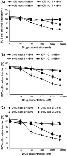
Figure 10. In vitro cytotoxicity of 30% 1C1-PEG23-, 60% 1C1-PEG23-, 30% mock-PEG23- and 60% mock-PEG23-SN38/m against PC3 cells after (A) 24, (B) 48 and (C) 72 h incubation. Data are shown as average ± SD from four experiments.

Table 4. IC50 values obtained after 6 h exposure to SN38-loaded micelles (SN38/m) installed with 1C1- or mock Fab-linkers prepared with PEG23 cross-linker, at post-incubation times of 24, 48 and 72 h.

Supplemental material