Figures & data
Figure 1. Study area: Lahore, Pakistan (A) towns in Lahore city and (B) towns selected for this study in Landsat-8 OLI false-colour composite imagery of 18 May 2013.
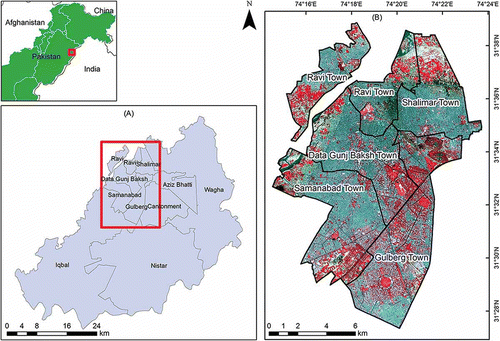
Figure 2. High-pass convolution filter kernel.
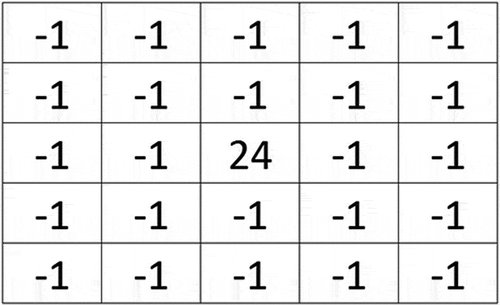
Figure 3. Landsat-8 OLI image in true-colour composite (A) before resolution merging (30 m spatial resolution) and (B) after resolution merging (15 m spatial resolution).
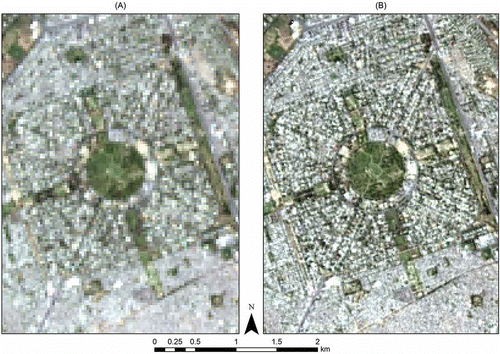
Figure 4. Reflectance of built-up, vegetation and water areas in (A) optical bands 2–7 (DN value) and (B) thermal bands 10–11 (temperature in degree Celsius) of Landsat-8 OLI image.
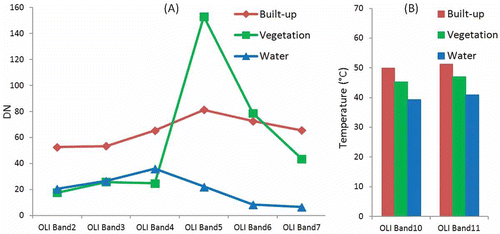
Figure 5. Scatter plots showing the correlation between (A) band 6 (x-axis) and band 7 (y-axis), and (B) band 10 (x-axis) and band 11 (y-axis) of the Landsat-8 OLI image.
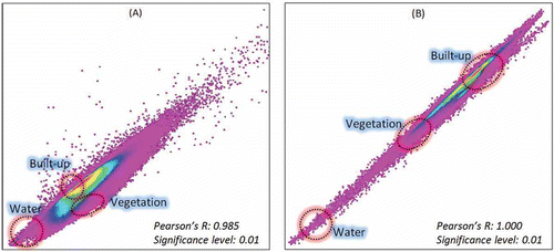
Figure 6. The resultant images of (A) NDBI, (B) NDVI and (C) MNDWI derived from the Landsat-8 OLI image.
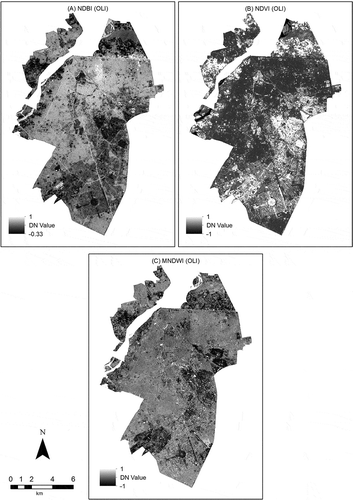
Figure 7. Scatter plots showing the correlation between (A) NDBI (x-axis) and NDVI (y-axis), (B) NDBI (x-axis) and MNDWI (y-axis), and (C) NDVI (x-axis) and MNDWI (y-axis).
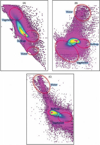
Table 1. The Pearson’s R values showing the degree of relationship among NDBI, NDVI and MNDWI.
Figure 8. Map showing (A) a continuous image of built-up areas derived by BAEM, and (B) segmented output of BAEM (built-up area extracted through segmentation of (A) using the threshold value from DFPS).
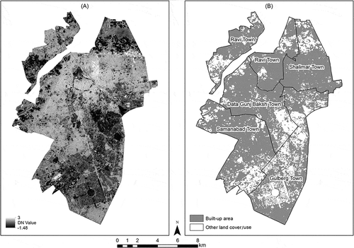
Table 2. Results of the double-window flexible pace search for the determination of the optimal threshold value.
Table 3. Error matrix for NDBI method and BAEM.
Table 4. Summary of the accuracy assessment of the images derived by NDBI method and BAEM.
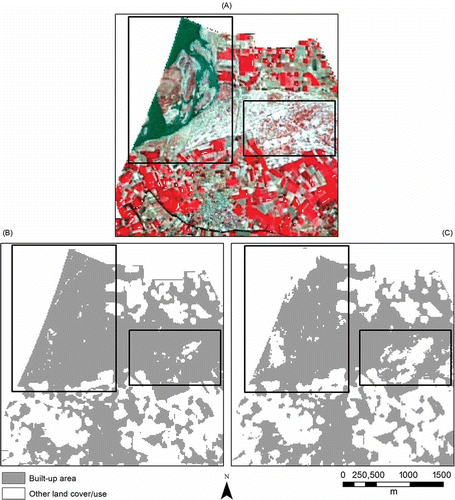
Figure 9. Comparison of the results from the NDBI approach and BAEM at a sample location (A) OLI image in false-colour composite, (B) output from NDBI approach and (C) output from BAEM. (Black rectangles in each panel show the places where the NDBI approach wrongly extracted other land covers as built-up areas.)
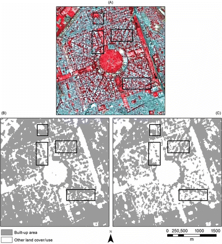
Figure 10. (A) OLI image in false-colour composite, (B) output from NDBI approach and (C) output from BAEM. (Black rectangles in each panel show the places that produced obvious commission errors in both methods.)