
Figures & data
Figure 1. (A) location of the SRW in the arid region of Northwest China. The red rectangle shows the location of the study area; (b) Landsat 8 image of the study area, outlined in red. The other boxes show the coverage of the SAR datasets. Landsat 8 imagery was acquired on 2021/06/10 and processed and provided by the U.S. Geological survey (USGS) (Brian, Markham, and Irons James Citation2013); (c) the digital elevation Model (DEM) of the study area, released in 2015 by the Japan Aerospace Exploration Agency (JAXA) (Takaku et al. Citation2016). The DEM is accessible at http://www.Eore.jaxa.jp/ALOS/en/aw3d30/. The red dots represent the locations of catalogued geological hazards; (d) a geological structure map of the study area. qh: holocene series, qp: pleistocene series, N: neogene System, J: jurassic System, P: permian System, C: carboniferous System, V: Gabbro; (e) characterization of the landforms in vertical gradient zone. 1: high mountain areas, 2: subalpine areas, 3: mid-mountainous belt, 4: foreland hills, 5: plains oasis area, 6: desert areas.
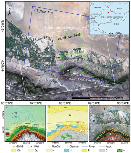
Table 1. Basic parameters of SAR datasets.
Table 2. The geographical information of the observation sites.
Figure 2. The sequential data processing workflow implemented in this study. S1-A and S1-D are abbreviations for Sentinel-1-ascending and Sentinel-1-descending, respectively.
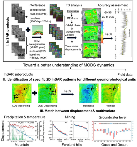
Figure 3. Interferometric baseline configurations of the three SAR datasets.
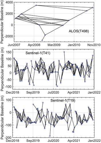
Figure 4. Displacement rates from (a) ALOS-ascending, (b) S1-A, and (c) S1-D in the LOS directions of the SRW.
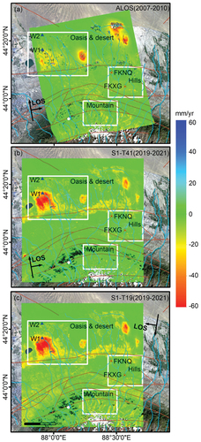
Figure 5. Surface characteristics corresponding to deformation monitored by ALOS datasets (2007–2010), (a) mountains, (b) hills, and (c) oases.
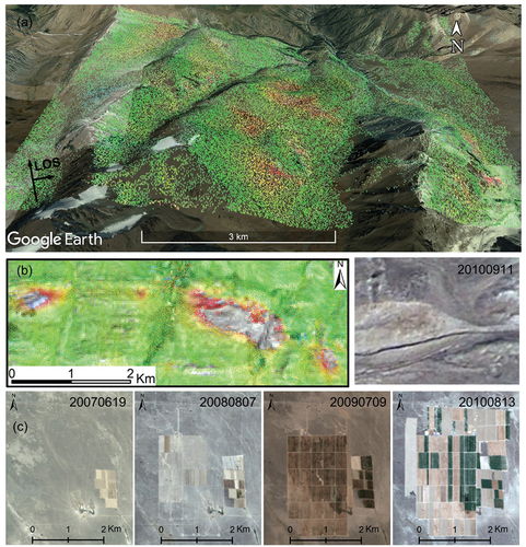
Figure 6. The time-series InSAR result (green squares) compared with the GNSS observation (gray squares).
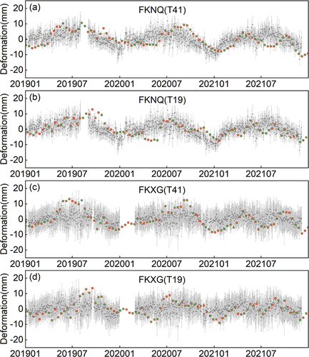
Figure 7. Average deformation of the subalpine area from 2019 to 2021. Linear deformation rates in LOS direction are from (a) ascending track 41 and from (b) descending track 19. Negative values in (a) and (b) indicate movement away from the satellite and positive values indicate movement toward the satellite. (c) horizontal (east-west), and (d) vertical deformation rate maps. The negative values in (c) and (d) represent westward and downward movements, respectively.
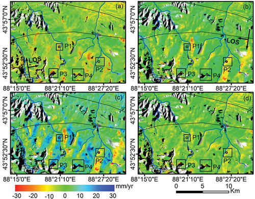
Figure 8. Displacement rates from (a), (b) eastward and (c), (d) vertical directions of the P1 and P2 slopes. Optical image from google Earth™, acquired on September 16, 2019; cross-sections (e) AA’ and (f) BB’ of P1 and P2, locations of the profiles is marked in ), respectively; time-series displacement in the LOS direction for P1(g) and P2(h).
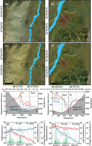
Figure 9. Displacement rates from (a), (b) eastward and (c), (d) vertical directions of the P3 and P4 slopes. Optical image from google Earth™, acquired on September 16, 2019; time-series displacement in the LOS direction for the P3(e) and P4(f).
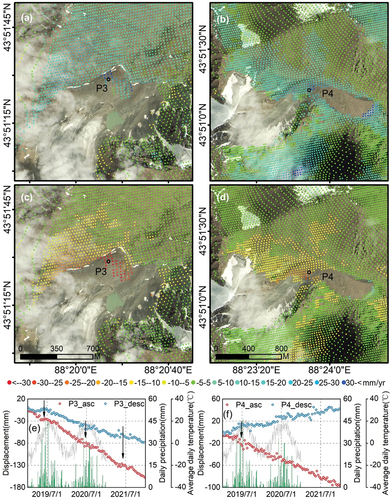
Figure 10. Velocity field in the foreland hills. The LOS average velocity from (a) S1-A and (b) S1-D was measured with InSAR time series. The orange points are the locations of catalogued geological hazards.
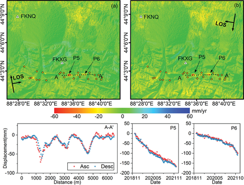
Figure 11. Displacement rates from (a) S1-vertical, (b) S1-horizontal (west-east), and (c) ALOS-vertical directions for the oasis and desert. Landsat 8 imagery (acquired on 2021/06/10) corresponding to W1 and W2 was processed and provided by the USGS. The black circles around W1 and W2 have a radius of 1500 meters.
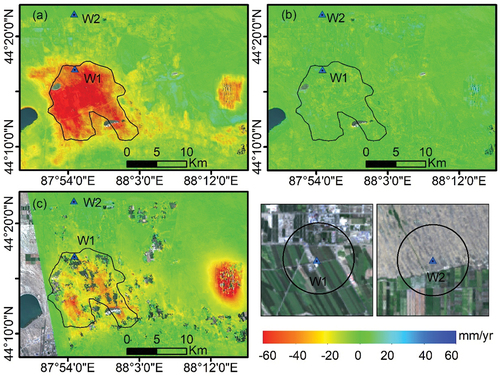
Figure 12. The time-series InSAR vertical displacements in comparison with the GWL in W1 and W2.
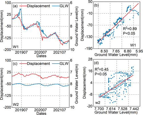
Figure 13. The displacement changes correspond to the GWL changes, with a time scale of 5 days (interpolating the displacement time series to the corresponding groundwater observation dates).
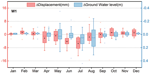
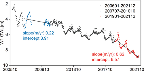
Figure 14. The GWL in W1 from 2006 to 2021.
Data availability statement
Data used in this study is available upon reasonable request to the first author Binbin Fan ([email protected])