247
Views
5
CrossRef citations to date
0
Altmetric
Original Articles

Inverse thermal problems in computational modelling of the paper vacuum drying process

, , &
Pages 59-73 | Received 02 Sep 2010, Accepted 06 Oct 2010, Published online: 24 Jan 2011

Figures & data

Table 1. Values of parameters in modified Henderson sorption isotherm model.

Figure 1. Relative sensitivity coefficients of temperature field after 100 s after beginning of the vacuum period with respect to heat conduction coefficient (a), evaporation constant (b), lumped diffusion coefficient of water in paper (c) and specific heat capacity (d).
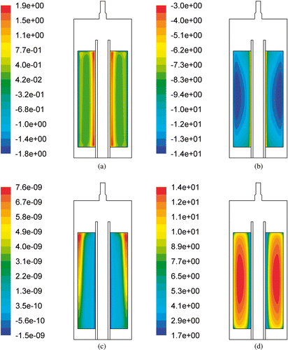
Figure 1. Relative sensitivity coefficients of temperature field after 100 s after beginning of the vacuum period with respect to heat conduction coefficient (a), evaporation constant (b), lumped diffusion coefficient of water in paper (c) and specific heat capacity (d).

Figure 2. Parts of the paper vacuum drying experimental stand: (a) vacuum chamber and (b) paper coil with thermocouples.
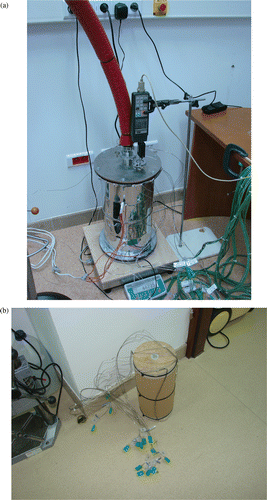
Figure 2. Parts of the paper vacuum drying experimental stand: (a) vacuum chamber and (b) paper coil with thermocouples.

Figure 3. Thermocouples arrangement within (a) the paper coil and (b) initial temperature field. Dimensions are in millimetres and temperatures are in degrees Celsius.
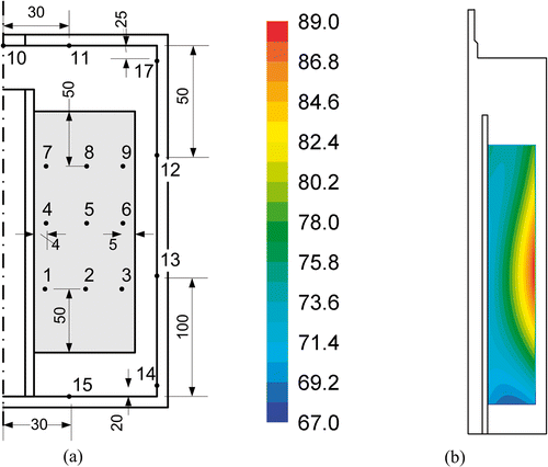
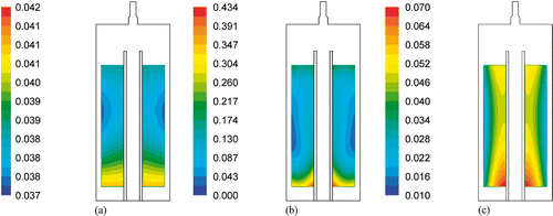
Figure 3. Thermocouples arrangement within (a) the paper coil and (b) initial temperature field. Dimensions are in millimetres and temperatures are in degrees Celsius.
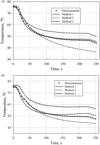
Table 2. Results of the inverse analysis.

Figure 4. Initial moisture distribution obtained with: (a) the first approximation approach, (b) the second approximation approach and (c) the third approximation approach.

Figure 4. Initial moisture distribution obtained with: (a) the first approximation approach, (b) the second approximation approach and (c) the third approximation approach.

Figure 5. Comparison of temperature histories obtained for the first, the second and the third approximation approach with the measurements at points no 2: (a) the best fitting and 3 (b) the worst fitting.

Figure 5. Comparison of temperature histories obtained for the first, the second and the third approximation approach with the measurements at points no 2: (a) the best fitting and 3 (b) the worst fitting.

Reprints and Corporate Permissions

Please note: Selecting permissions does not provide access to the full text of the article, please see our help page How do I view content?

To request a reprint or corporate permissions for this article, please click on the relevant link below:

Academic Permissions

Please note: Selecting permissions does not provide access to the full text of the article, please see our help page How do I view content?

Obtain permissions instantly via Rightslink by clicking on the button below:

If you are unable to obtain permissions via Rightslink, please complete and submit this Permissions form. For more information, please visit our Permissions help page.