
Figures & data
Figure 1. Preferred sites for intramuscular (IM) injections in the human body. Depending on volume of injectate to be administered, IM injections are performed into the mass of the A) deltoid muscle, B) rectus femoris, vastus lateralis, or C) the dorsogluteal plane of the gluteus medius muscle. The gluteus maximus muscle, though no longer recommended for IM injections, due to risk of sciatic nerve damage, is shown here for context.
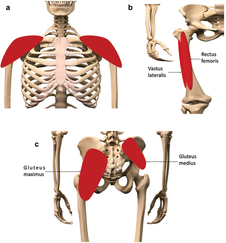
Figure 2. The structure, and fascial layers of, the skeletal muscle organ. The fascial layers provide structural support for the functional elements of the skeletal muscle, whilst retaining sufficient elasticity to adapt to conformational changes within the organ during dynamic movement. Reproduced from [10] with permission.
![Figure 2. The structure, and fascial layers of, the skeletal muscle organ. The fascial layers provide structural support for the functional elements of the skeletal muscle, whilst retaining sufficient elasticity to adapt to conformational changes within the organ during dynamic movement. Reproduced from [10] with permission.](/cms/asset/d2e6b773-7846-4c30-b0d9-9240cc532854/iedd_a_2388841_f0002_c.jpg)
Figure 3. Distribution of material post-IM injection. A, B) 1 mL of an oil vehicle (10% benzyl alcohol and 90% sesame oil was injected into A) the deltoid and B) vastus lateralis muscles of a human volunteer. Immediately following administration, the resulting depots (approx. length 5 cm), distributing along fascial planes, were visualised with 3-dimensional graphics. Adapted from [34] with permission. C) After injection of cabotegravir (40 mg/kg dose, 200 mg/mL stock) into rat “upper hindlimb” muscle, a depot formed of approx. 2 mm diameter. Distribution of drug from this central depot followed discreet routes following interfascial planes, highlighting a “path of least resistance” for the injected material. Adapted from [35] with permission.
![Figure 3. Distribution of material post-IM injection. A, B) 1 mL of an oil vehicle (10% benzyl alcohol and 90% sesame oil was injected into A) the deltoid and B) vastus lateralis muscles of a human volunteer. Immediately following administration, the resulting depots (approx. length 5 cm), distributing along fascial planes, were visualised with 3-dimensional graphics. Adapted from [34] with permission. C) After injection of cabotegravir (40 mg/kg dose, 200 mg/mL stock) into rat “upper hindlimb” muscle, a depot formed of approx. 2 mm diameter. Distribution of drug from this central depot followed discreet routes following interfascial planes, highlighting a “path of least resistance” for the injected material. Adapted from [35] with permission.](/cms/asset/b502a064-7ed1-4051-95c5-8cdac6e3d7b0/iedd_a_2388841_f0003_c.jpg)
Figure 4. Movement of the interstitial fluid (ISF) in vivo. A) As blood transfers from arterial to venous vessels through tissue beds, B) blood pressure forces plasma fluid out of the systemic circulation into the tissue, generating interstitial fluid. C) As these forces are exceeded by osmotic gradients, the extravasated fluid begins to return to the venous end of the local vasculature. D) Some of this fluid is taken up by the lymphatic system, carrying lipophilic elements, e.g., proteins and drugs. In skeletal muscle, the dynamic movement of the local tissues, and pulse pressure of local arterioles, provides the necessary forces to move the lymph through the one-way bicuspid valves of the lymphatic system.
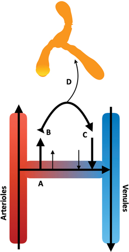
Table 1 Composition of interstitial fluid mimicking solutions.
Table 2 Collagenous motif amino acid content, per 1000 amino acids, of bovine type-I collagen (Col1) and acid-extracted (type A) bovine gelatin. Adapted from [97].
Table 3 Acellular post-intramuscular injection events.
Figure 5. The Simulator of IntraMuscular Injections (SIMI) research tool. (A) A polystyrene float (1) suspends a type-I collagen and hyaluronic acid hydrogel, contained within a semi-porous cuvette (2). The hydrogel-containing cuvette is suspended in interstitial fluid (ISF)-mimicking solution, maintained at 37 ◦C, pH 7.4 (3). This ISF mimic is constantly stirred via magnetic stirring (4) to mimic ISF movement in vivo using a heated stirring plate (5). (B) Materials are injected into the centre of the hydrogel at a 90o angle relative to the surface, forming a bolus deposit. (C) Over time, injected material traverses (and interacts with) the collagen/hyaluronic acid matrix. The injected material then exits the matrix and moves across the non-specific membranes, releasing into the buffer system. Reproduced from [59] with permission.
![Figure 5. The Simulator of IntraMuscular Injections (SIMI) research tool. (A) A polystyrene float (1) suspends a type-I collagen and hyaluronic acid hydrogel, contained within a semi-porous cuvette (2). The hydrogel-containing cuvette is suspended in interstitial fluid (ISF)-mimicking solution, maintained at 37 ◦C, pH 7.4 (3). This ISF mimic is constantly stirred via magnetic stirring (4) to mimic ISF movement in vivo using a heated stirring plate (5). (B) Materials are injected into the centre of the hydrogel at a 90o angle relative to the surface, forming a bolus deposit. (C) Over time, injected material traverses (and interacts with) the collagen/hyaluronic acid matrix. The injected material then exits the matrix and moves across the non-specific membranes, releasing into the buffer system. Reproduced from [59] with permission.](/cms/asset/ea0e00bd-57a5-4d98-88da-29858ff71969/iedd_a_2388841_f0005_c.jpg)
Figure 6. The ex vivo skeletal muscle model for studying nanoparticle fate post-intramuscular injection. Fluorescently-labelled nanoparticles were injected into a whole, intact mouse soleus muscle, close to the tendon. The distribution of the nanoparticles was studied via cryosections of the proximal region over increasing timeframes. Reproduced from [138] under Commons Licence CC BY-NC 4.0.
![Figure 6. The ex vivo skeletal muscle model for studying nanoparticle fate post-intramuscular injection. Fluorescently-labelled nanoparticles were injected into a whole, intact mouse soleus muscle, close to the tendon. The distribution of the nanoparticles was studied via cryosections of the proximal region over increasing timeframes. Reproduced from [138] under Commons Licence CC BY-NC 4.0.](/cms/asset/ec4bf0b3-4a13-4ff0-a672-910d40128786/iedd_a_2388841_f0006_c.jpg)