Figures & data
Figure 1. Printed ceramic crowns after: (a) printing, (b) debinding, (c) sintering and (d) cleaning & removal of support structure.
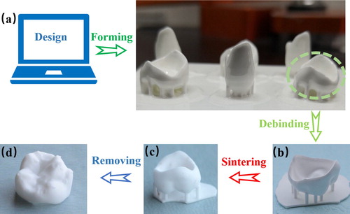
Figure 2. Optimisation of the debinding and sintering process. (a) TG-DSC curve of the hybrid slurry. (b) Scheme of an optimised debinding and sintering process.
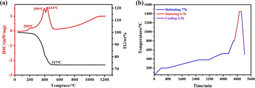
Table 1. Measured sizes along three axes of the as-printed and sintered specimens.
Figure 3. Thickness measurement on the edge of a stereolithography-fabricated ceramic crown after sintering.
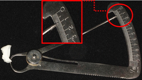
Figure 4. Deterioration on surface quality. (a) Scheme of ‘ladder effect’, (b) the stepwise contour on the occlusal surface of the printed crown, (c) remnant of support structure on the occlusal surface.
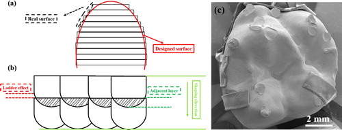
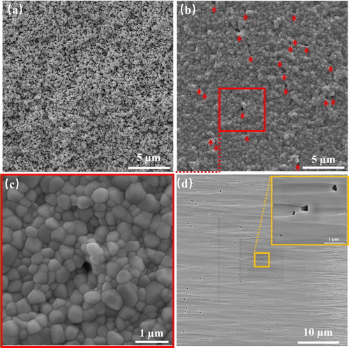
Figure 5. Densification of stereolithography-fabricated ceramic prostheses investigated by SEM. (a) The surface of sample after debinding showing pore network. (b & c) The surface of sample after sintering. (d) The argon ion beams polished cross section revealing the presence of residual pores.