Figures & data
Figure 1. Hydraulic schematic of the actuator prototype.
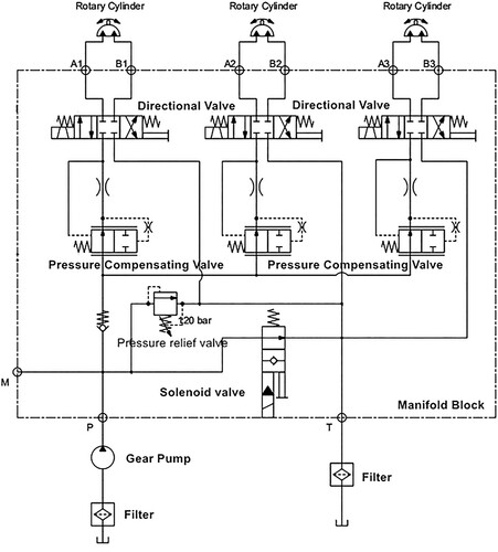
Figure 2. A progressive design for AM method in the system-level.
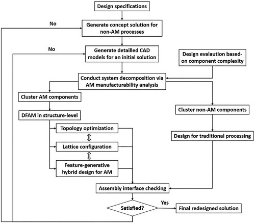
Figure 3. Initial design without oil pipe connection for traditional manufacturing processes.
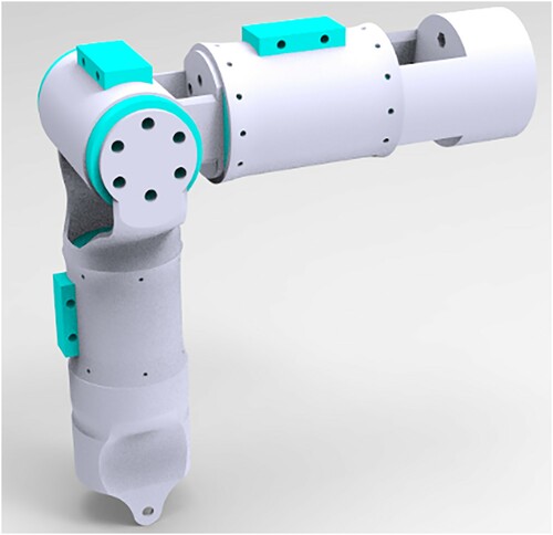
Figure 4. System decomposition for AM and non-AM processing.
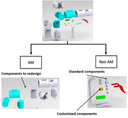
Figure 5. Structure redesign for AM via combined design for AM methods: a. TO combines with generative design; b. TO combines with lattice configuration.
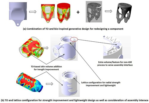
Figure 6. Redesigned components of the AM component group of the actuator system (left) and the full actuator system (right).
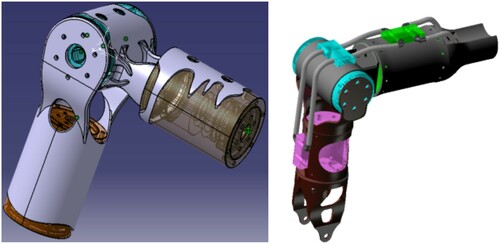
Figure 7. Example of consideration on strength and AM constraints for design adaptation.
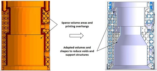
Figure 8. (a) Ti200 double-laser machine; (b) scanning electron microscopy image of Ti6Al4 V powder.
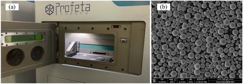
Table 1. Main printing parameter settings.
Figure 9. Printed components.
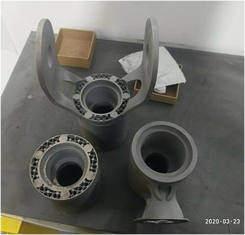
Figure 10. Annealing process curve for the printed components in Ti6Al4V material.
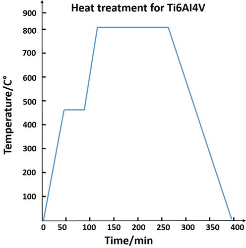
Figure 11. Schematic of the mechanical arm structure.
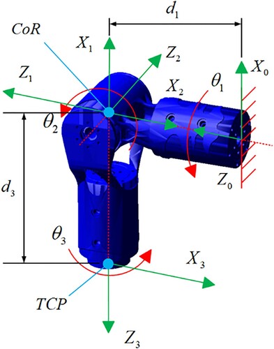
Figure 12. Position of TCP distributed on a special spherical surface.
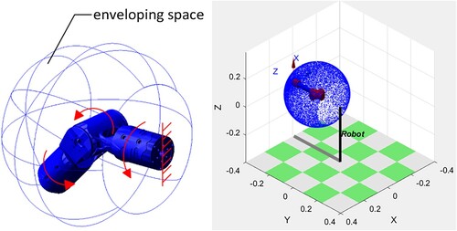
Figure 13. Simulation curves of the position relationship between the TCP in space and the driving joint.
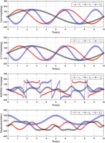
Figure 14. Four representative orientations of the 3-DOF robot actuator.
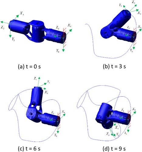
Table 2. Parameter values of the 3-DOF robot actuator.
Figure 15. Single-joint motion range experiment.
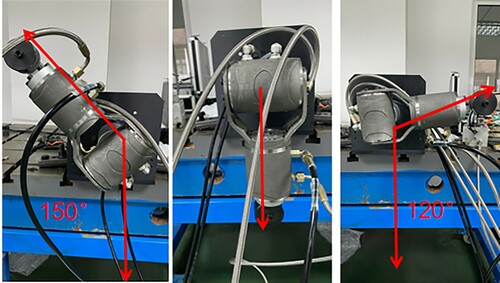
Figure 16. Prototype dimension measurement as part of the testing.
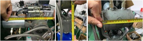
Figure 17. Weight measurement.
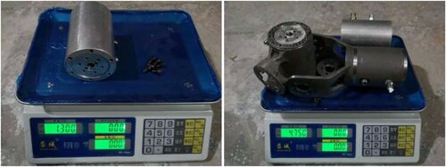
Figure 18. Torque measurement experiment.
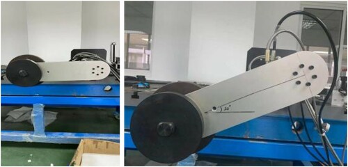
Figure 19. Application scenario test.
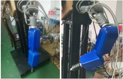
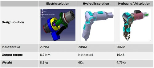
Figure 20. Solution comparison.