
Figures & data

Figure 1. Summary of major topology optimisation and metal additive manufacturing techniques. Metal AM portion adapted from (Kok et al. Citation2018).
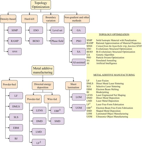
Figure 2. The application of TO and MAM in the development of aircraft brackets as developed by (a) (Seabra et al. Citation2016). Reproduced with permission from Ref. (Seabra et al. Citation2016). Copyright 2016, Elsevier, and (b) (López-Castro et al. Citation2017). Reproduced with permission from Ref. (López-Castro et al. Citation2017). Copyright 2017, Elsevier.
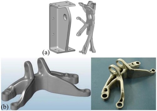
Figure 3. Topology-optimised prostheses for four resection types. Reproduced with permission from Ref. (Iqbal et al. Citation2019). Copyright 2019, Elsevier.
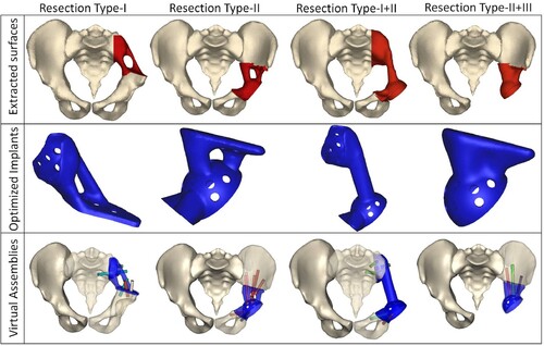
Figure 4. Major applications of TO and MAM in medicine: mandibles (reproduced with permission from Ref. (Li et al. Citation2020a). Copyright 2020, Elsevier), cranium and facial (Park et al. Citation2021), pelvic and hip (reproduced with permission from Ref. (Iqbal et al. Citation2019). Copyright 2019, Elsevier), dental (reproduced with permission from Ref. (Park et al. Citation2019). Copyright 2019, Elsevier), and spine (reproduced with permission from Ref. (Wang et al. Citation2020a). Copyright 2020, Elsevier).
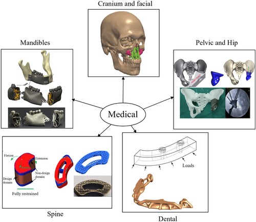
Figure 5. Applications of TO and MAM in the automotive industry: (a) brake calliper (Tyflopoulos et al. Citation2021), (b) upright design (Hunar et al. Citation2020), (c) diesel engine support (Marchesi et al. Citation2015).
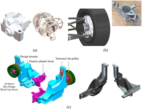
Figure 6. Application of TO and MAM in other industries (a) redesign of a welding jig (reproduced with permission from Ref. (Schuh et al. Citation2020). Copyright 2020, Elsevier) design of a phase change material-based heat sink (reproduced with permission from Ref. (Ho et al. Citation2021). Copyright 2021, Elsevier).
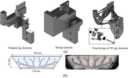
Figure 7. Cost and energy estimations for producing three parts using conventional machining (CM) and a hybrid electron beam melting (EBM) and finish machining (FM). Adopted from (Priarone et al. Citation2017).
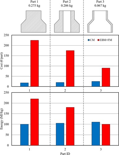
Figure 8. Chart organisation of (a) topology optimisation models, (b) optimisation objectives, (c,e) materials, and (d,f) MAM processes across the aerospace, medical, automotive, and other industries.
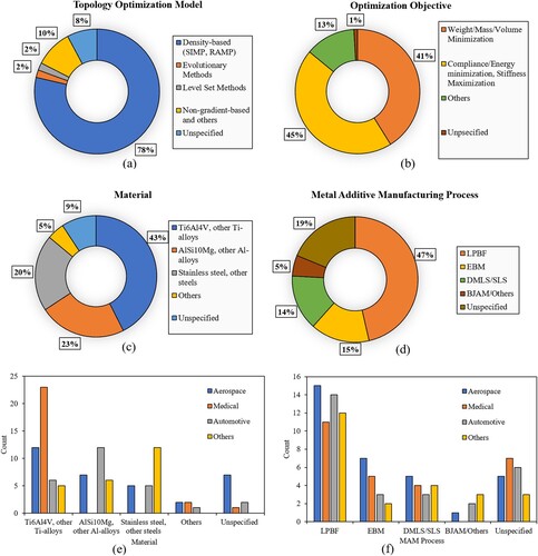
Figure 9. Types of support structures under overhang areas in different parts. (a) vertical strut-type supports (b) honeycomb supports (Zhang et al. Citation2020a) (c) porous-type support (obtained with permission from GE Additive) (d) contact-free support (Cooper et al. Citation2017) (e) topology-optimised support (Langelaar Citation2019).
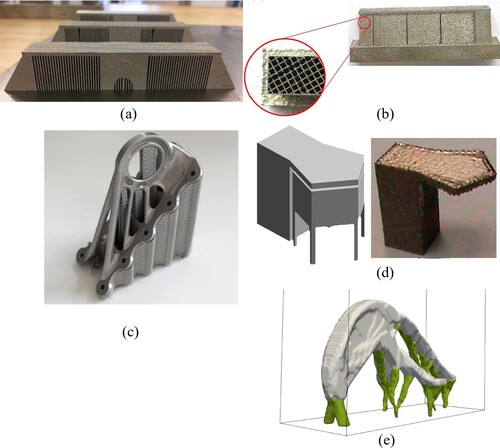
Figure 10. (a) Different orientations resulting in different support structure volumes (Di Angelo et al. Citation2020). Optimisation of build orientation to minimise residual stresses using cubic lattice structure, (b) optimal orientation with cubic lattices (c) normalised residual stresses after process simulation. Reproduced with permission from Ref. (Cheng and To Citation2019). Copyright 2019, Elsevier.
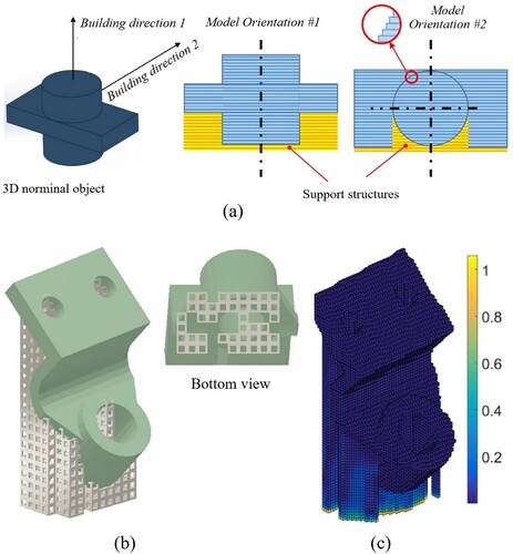
Figure 11. Optimised support structures considering maximum heat dissipation, (a) results from Zhou et al. (Zhou et al. Citation2019a). Reproduced with permission from Ref. (Zhou et al. Citation2019a). Copyright 2019, Elsevier., (b) results from Miki and Nishiwaki (Miki and Nishiwaki Citation2022). Reproduced with permission from Ref. (Miki and Nishiwaki Citation2022). Copyright 2022, Elsevier.
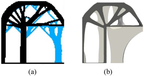
Figure 12. Workflow process for the implant component. (a) Specimen for printing, (b) voxel-based mesh for analysis, (c) Optimised density profile of support structure, and (d) Optimal lattice support along with CAD model of the component. Reproduced with permission from Ref (Cheng et al. Citation2019a). Copyright 2019, Elsevier.
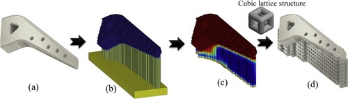
Figure 13. Support TO results designed by Zhang et al. (Citation2020a) considering the MAM process to reduce part deflection. (a) Original Equipment Manufacturer support, (b) support optimised for part gravity load only, (c) support optimised for both part gravity and residual stress from AM process. Reproduced with permission from Ref (Zhang et al. Citation2020a). Copyright 2020, Springer Nature.
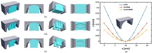
Table 1. Summary of efforts on support structure TO.
Figure 14. Topology optimised cantilever design with distortion and recoater collision constraints (far left), x and y displacement plots of the resulting topology (middle and far right image respectively) (Misiun et al. Citation2021).
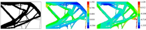
Table 2. Summary of review papers on MAM modelling.
Figure 15. The application of overhang or self-supporting constraints in (a) the B-spline parameterised TO. Reproduced with permission from (Wang et al. Citation2021b). Copyright 2021, Elsevier, (b) the BESO-based TO. Reproduced with permission from (Bi et al. Citation2020). Copyright 2020, Elsevier.
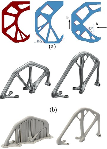
Figure 16. An LPBF-manufactured topology-optimised framework before and after support removal.
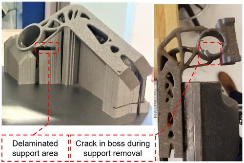
Figure 17. Force line method and resulting lattice for a beam in bending as described in Daynes et al. (Citation2017). Reproduced with permission from (Daynes et al. Citation2017). Copyright 2022, Elsevier.
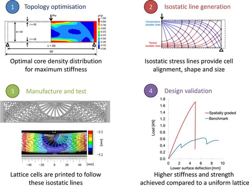
Figure 18. Application of deep-learning-based models (a) CNN used for prediction of optimised structures from intermediate topologies (Sosnovik and Oseledets Citation2019) (b) GANs for TO (Rawat and Shen Citation2018).
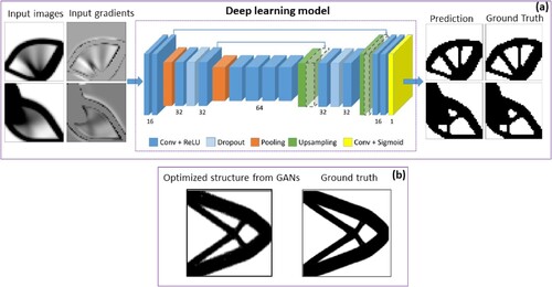
Figure 19. A PATO framework to integrate additive manufacturability in the part design process through a deep neural network predictor (Naresh et al. Citation2021).
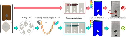
Figure 20. TO workflow with major steps. (a) Pre-processing design space and boundary condition defining using a color-coding representation (Ibhadode et al. Citation2021) and a voxelization approach (Zhang et al. Citation2021) (reproduced with permission from (Zhang et al. Citation2021). Copyright 2021, Springer Nature) (b) topology optimised models (Ibhadode et al. Citation2021; Zhang et al. Citation2021) (c) Post-processing step to smoothen a topology optimised connecting rod model generated in nTopology (nTopology Citation2023) (d) Different length scales and models required to model MAM processes. Reproduced with permission from (Francois et al. Citation2017). Copyright 2017, Elsevier. (e) Prediction of hot and cold defects for PBF processes using a probability of thermal errors. Reproduced with permission from (Moran et al. Citation2021). Copyright 2021, Elsevier.
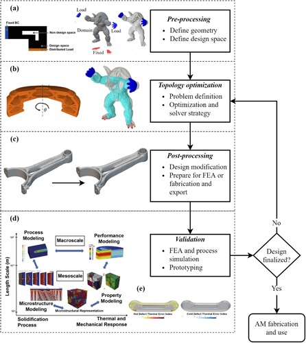
Table 3. Commercial TO software with multiple functionalities of interest.