
Figures & data
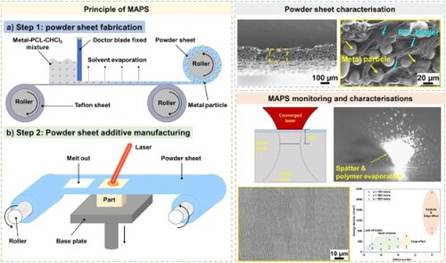
Figure 1. Main issues that are limiting the wide uptake of LPBF.
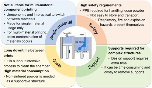
Figure 2. Schematic illustration of powder sheet fabrication process (a) and MAPS manufacturing by using feedstock of powder sheet (b).
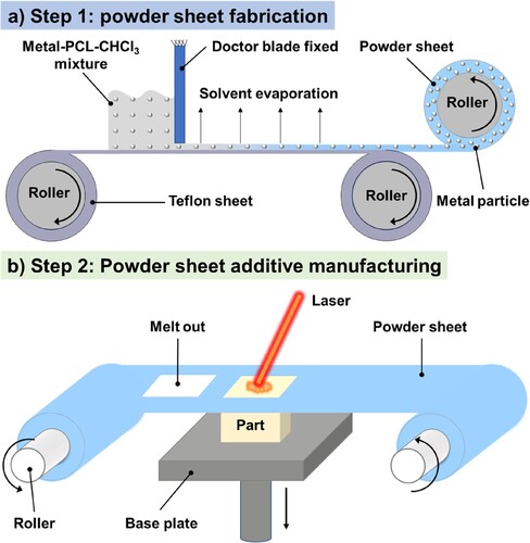
Table 1. Chemical composition of SS304 loose powder (wt. %).
Figure 3. The illustration of defocus for MAPS printing (a). The relationship between laser spot diameter and defocus, which is calculated based on reference [Citation40] (b). Power density distribution (z = 0) with different defocuses: (c) 0 mm. (d) −3 mm. (e) −4 mm. (f) −5 mm. (g) −6 mm. (h) −7 mm.
![Figure 3. The illustration of defocus for MAPS printing (a). The relationship between laser spot diameter and defocus, which is calculated based on reference [Citation40] (b). Power density distribution (z = 0) with different defocuses: (c) 0 mm. (d) −3 mm. (e) −4 mm. (f) −5 mm. (g) −6 mm. (h) −7 mm.](/cms/asset/7a1e2681-27f3-46bd-8c9e-43fc073a5ee4/nvpp_a_2361856_f0003_oc.jpg)
Table 2. Process parameters used for printing functional components.
Figure 4. Manufactured SS304 powder sheet and SEM characterisations. (a) Photo of a rollable and flexible powder sheet. SEM observation of cross-section (b) with a higher magnification (c), top surface (d) with a higher magnification (e), and bottom surface (f) with a higher magnification (g) of powder sheet.
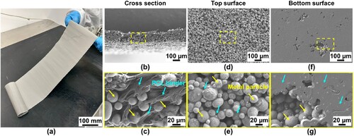
Figure 5. (a) TGA of SS304 powder sheet. (b) Absorption spectra for SS304 powder sheet and pure PCL polymer sheet, measured from each side.
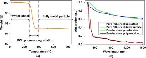
Figure 6. OM observations of melt pool morphology of single lines printed using a constant scanning speed of 100 mm/s and laser power of 100 W with different defocus settings: (a) 0 mm, (b) −3 mm, (c) −4 mm, (d) −5 mm, (e) −6 mm and (f) −7 mm. (g) Statistics of the melt pool morphology with S represents laser spot diameter, H represents melt pool depth above the base plate, D means melt pool depth below the base plate and W means the melt pool width.
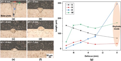
Figure 7. Comparison of high-speed imaging for MAPS printing and evolution with time at no defocus (0 mm, a-c) and negative defocus setting of −6 mm (d-f). (a) and (d) at 0.667 ms. (b) and (e) at 10 ms. (c) and (f) at 50 ms.
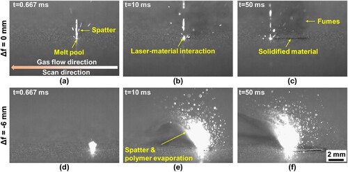
Figure 8. High-speed imaging for MAPS printing at defocuses of 0 mm (a-c) and −6 mm (d-f) and three different scanning speeds of 100 mm/s, 300 mm/s, and 500 mm/s, respectively. (a) and (d) for 100 mm/s. (b) and (e) for 300 mm/s. (c) and (f) for 500 mm/s.
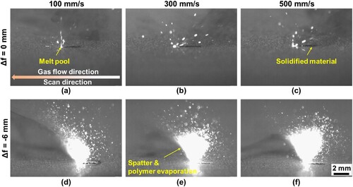
Figure 9. High-speed images by six different defocus settings: (a) 0 mm. (b) −3 mm. (c) −4 mm. (d) −5 mm. (e) −6 mm. (f) −7 mm.
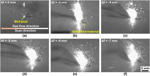
Figure 10. SEM observation at the top surface of SS304 samples printed by different scanning speeds (100, 300 and 500 mm/s) and defocus settings (0, −3, −4, −5, −6 and −7 mm).
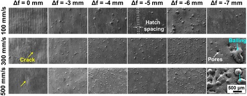
Figure 11. Optical micrographs of polished cross sections showing geometry and density of SS304 samples printed by different scanning speeds (100, 300 and 500 mm/s) and defocus settings (0 mm, −3 mm, −4 mm, −5 mm, −6 mm, and −7 mm).
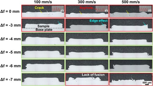
Figure 12. (a) The relationship of 30-layer SS304 sample’s total height and defocus and scanning speed. (b) Relative density of samples manufactured by different defocus settings and scanning speeds. (c) Open window for MAPS printing with different scanning speeds and defocus settings.
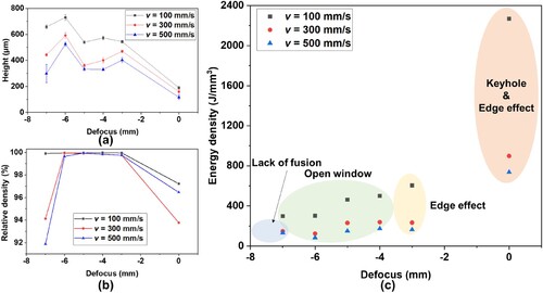
Figure 13. SEM observation of electrochemically etched 30-layer SS304 samples printed with different defocus settings: (a) and (d) 0 mm defocus. (b) and (e) −4 mm defocus. (c) and (f) −6 mm defocus.
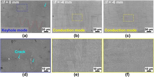
Figure 14. EDX analysis for the chemical composition of the MAPS printed SS304: line analysis (a), mapping for the Fe element (b), mapping for the C element (c). XRD comparison of MAPS printed SS304 with loose powder (d).
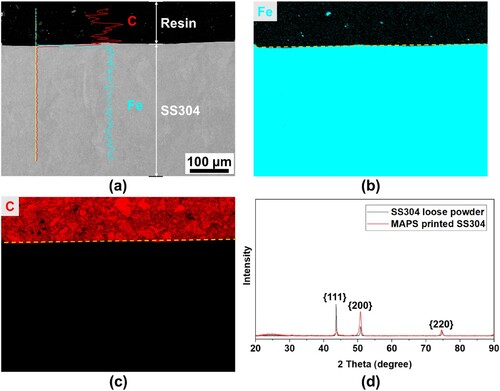
Figure 15. EBSD orientation maps perpendicular to the build direction for 0 mm no defocus setting (a), −4 mm defocus setting (b) and −6 mm defocus setting(c). The ternary chart with colours corresponds with crystallographic orientations for austenite.
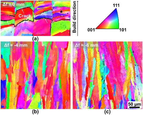
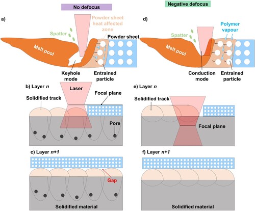
Figure 16. Schematic illustration of the defocus setting effect on MAPS printing: no defocus setting (a-c) and negative defocus setting (d-f).
Data availability statement
The authors confirm that the data supporting the findings of this study are available within the article.